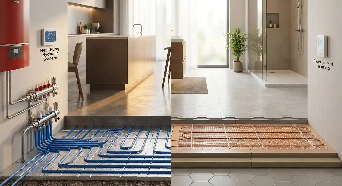
Underfloor heating is often discussed as a single product category, yet electric resistive matting and hydronic pipework driven by a heat pump are fundamentally different energy systems that happen to share a floor build-up. One converts electricity to heat at a fixed one-to-one ratio. The other uses electricity to move ambient heat, multiplying the delivered output several times over. For clean-tech property investors, building services engineers and smart-home designers, the choice shapes both capital expenditure and the lifetime operating cost of the asset.
| Parameter | Electric resistive matting | Hydronic (wet) underfloor with air source heat pump |
|---|---|---|
| System type | Resistive heating cable or mesh embedded in a thin adhesive or levelling layer, powered directly from the consumer unit. | Polyethylene or multilayer pipework in a screed or routed panel, fed by a manifold and low-temperature heat pump. |
| Installation cost barrier | Low. Mat cost and an electrician's circuit; typically the cheapest route per room, with little disruption. | High. Excavation or screed, insulation, manifold, pump group, controls and heat pump; usually part of a whole-house project. |
| Operational efficiency (COP) | 1.0: 1 kW of electricity yields 1 kW of heat. | Typically 3.5 to 4.5 at 30°C to 35°C flow, exceeding 4.0 in mild conditions. |
| Compatibility with primary heat pumps | None. It is an independent electrical load and does not use a heat pump. | Excellent. Large emitter area allows low flow temperatures, which is the ideal operating point for an air source heat pump. |
| Thermal storage capacity | Low in thin-bed builds (a few millimetres of adhesive); moderate only if embedded in a thick screed. | High. A 65 to 75 mm screed encapsulating the pipework acts as a substantial energy sink. |
| Ideal application profile | Single-room retrofits, bathrooms, extensions and supplementary comfort heating with limited heat demand. | New builds, deep retrofits and whole-house systems where the fabric is well insulated and the floor can be lifted. |
The COP running cost penalty
The operational divide is arithmetic before it is engineering. An electric resistive system consuming 1 kW of grid energy yields exactly 1 kW of thermal output: its Coefficient of Performance is 1.0, and there is no mechanism by which it can do better. A hydronic setup leveraging an ambient heat pump transforms that same 1 kW of electrical input into 3.5 to 4.5 kW of domestic space heating, because the compressor transfers heat from outdoor air rather than generating it.
At a notional unit price of 25 pence per kWh, every kilowatt-hour of heat from resistive matting costs 25 pence. At a COP of 4.0, the same kilowatt-hour of heat costs approximately 6.25 pence, a reduction of 75 per cent. For a room requiring 3,000 kWh of heat annually, that is the difference between about £750 and about £188 in running costs, before any tariff optimisation. Over a 15 to 25 year asset life the cumulative gap can exceed the entire installation premium of the wet system, which is why total cost of ownership, not purchase price, should drive the specification of whole-house systems.
This efficiency is not constant. A heat pump's COP declines as the temperature lift between source and sink increases, so the benefit relies on keeping flow temperatures low. Underfloor emitters are ideal for this. The large radiating surface, often covering most of the floor area, can deliver the required output at flow temperatures of 30°C to 35°C, where a conventional radiator would need 45°C to 55°C or more. Lower flow temperature means lower compressor lift, and so the 4.0-plus COP figures cited above. Resistive matting has no such sensitivity: it delivers a COP of 1.0 irrespective of the weather, which is stable but permanently expensive.
Thermal mass storage arbitrage
Time-of-use tariffs introduce a second variable. If electricity costs a fraction of the standard rate overnight, a heating system able to store heat during that window and release it during the day can reduce the effective unit cost significantly. The ability to do so depends on physical thermal mass, not on the type of heating element.
Thin-bed electric floor installations lack the structural mass to retain heat. A mat embedded in a few millimetres of tile adhesive responds quickly, usually within 30 to 60 minutes, but its storage capacity is small: when the power is cut, the floor cools almost as quickly as it warmed. Such a system is effectively a real-time heater, and shifting its load into cheap periods would leave the room cold when the occupants are awake and paying peak rates.
Thick liquid screeds encapsulating hydronic pipework behave very differently. A 65 to 75 mm flowing screed has a specific heat capacity of roughly 0.84 kJ per kg per kelvin and a density of around 2,000 kg per cubic metre. For 1 square metre of screed at 70 mm, that is approximately 140 kg of material; raising its temperature by 3 K stores around 0.1 kWh of heat per square metre. In a 50 square metre ground floor, that amounts to approximately 5 kWh of stored energy for a modest 3 K swing, and more with a broader permitted temperature band. This is a high-capacity energy sink that can be pre-heated during cheap off-peak hours and coast through peak-rate periods, with the slow thermal response acting as a natural buffer.
Electric systems can capture part of this benefit when installed in a thick screed rather than a thin adhesive bed, as in the traditional storage-heater model. In that configuration the matting is charged overnight and the slab releases heat gradually. This is a legitimate asset-optimisation strategy, but it carries a consequence: a thick slab heated by resistive elements still operates at a COP of 1.0. It lowers the unit cost through tariff arbitrage, but it cannot match the efficiency of a heat pump on the same slab, which combines a high COP with off-peak charging. In well-insulated homes the heat pump and screed combination is therefore the strongest option by a considerable margin.
The trade-off is controllability. A heavy screed has long thermal lag, sometimes many hours, so overshoot and undershoot are real risks without predictive control. Smart-home designers should specify weather-compensated, predictive controllers and room sensors that account for expected solar gain and forecast outdoor temperature, rather than simple thermostats that react after the room has already drifted from its set point.
Capital expenditure boundaries and installation friction
The case for electric matting rests entirely on installation economics. The dry, thin-profile mesh lays directly under tiles without raising floor profiles, typically adding only a few millimetres to the build-up. It requires an electrician to supply a dedicated circuit with a thermostat and floor sensor, and no plumbing, manifold or heat source. Installation can be completed within a day or two for a single room, with minimal disruption to the occupants. This low friction makes it the pragmatic choice for isolated renovations, bathrooms and extensions where a wet system would be disproportionate.
Wet engineering is a different order of intervention. A hydronic system typically requires excavation or removal of the existing floor to create depth for insulation and a screed, often 100 mm or more of total build-up. Insulation formatting is critical: without sufficient insulation beneath the pipes, a considerable share of the heat is lost downwards into the ground or structure rather than into the room. Pipework layout, normally in loops of 100 to 120 metres at 100 to 200 mm centres, must be designed to match the heat loss of each zone, with all loops returning to a manifold with flow meters and actuators. The manifold, a mixing or pump group, controls and the heat pump itself then complete the system. The finished floor must also be curing-compatible: screeds require a controlled heat-up sequence before floor coverings are laid, which adds time to the programme.
This is why the hydronic option is generally pursued in new builds and deep retrofits, where the floor is already open and the incremental cost of embedding pipework is small. Retrofitting wet underfloor heating into an occupied dwelling with a finished floor, low ceilings or limited threshold clearances is often technically possible using low-profile overlay panels, but capital cost, floor height and door adjustment typically rule it out.
Engineering verdict
The two technologies are not true substitutes. Electric matting is a low-capital, low-disruption comfort device whose running costs are fixed by its COP of 1.0, and is best deployed in small, intermittent-use or supplementary applications. Hydronic underfloor heating coupled to an air source heat pump is the only configuration that combines low flow temperatures, high COPs and meaningful thermal storage, and it is the correct specification for whole-house systems where the fabric performance is adequate and the floor can be opened.
For investors, the practical rule is to compare lifetime cost, not installation cost, and to reserve electric matting for rooms where the heat demand is low or the installation barrier of wet engineering cannot be justified. For building services engineers and smart-home designers, the design priority is to size the emitters for the lowest viable flow temperature, include sufficient insulation beneath the pipes, and use predictive controls to exploit the thermal mass of the screed against a time-of-use tariff.