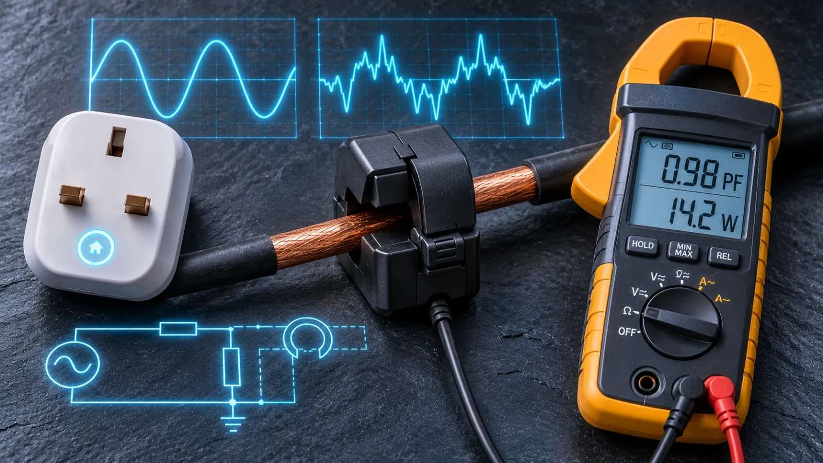
Hunting a home’s standby drain is a measurement problem before it is an energy problem. A modern household might leave 50 to 150 watts running around the clock: routers, set-top boxes, chargers, inverters, smart speakers and appliances in standby. Each is small, and the instruments used to find them are often least trustworthy at exactly the small currents involved. At 230 V, a 1 watt standby load draws about 4.3 milliamperes. Left on for a year it consumes 8.76 kWh, which at an assumed 27 pence per kilowatt-hour costs about £2.36. A cheap plug-in meter is being asked to resolve a few microvolts of signal across a milliohm resistor, in the presence of a current waveform that bears little resemblance to a sine wave. This article audits how that measurement is made, where each class of instrument fails, and which UK-available hardware suits which task. Figures marked as assumptions or typical values are modelling aids, not manufacturer specifications.
1. What a power meter actually measures
Real power is the time average of the product of instantaneous voltage and current, P = (1/T)∫v(t)i(t)dt. Apparent power is the product of the two RMS values, S = VrmsIrms. For distorted waveforms the relationship is S2 = P2 + Q2 + D2, where Q is the reactive power of the fundamental and D is the distortion power contributed by harmonic currents. The power factor is P/S. An instrument that measures only current, such as a clamp ammeter, can report S if it is told the voltage, but it cannot report P, because it has no way to know the phase relationship between the voltage and the current. That is the reason voltage-reference sampling is mandatory for watts.
The difference is large for the loads that dominate standby. A switch-mode power supply with a capacitor-input rectifier typically has a power factor of 0.45 to 0.65. A phone charger that draws 90 milliamperes RMS at 230 V presents 20.7 VA of apparent power, but at a power factor of 0.45 its real power is about 9.3 W. A meter that multiplies the current by a nominal 230 V and calls the result watts overstates the load by more than a factor of two. Equally, a current-only reading says nothing about the energy that will appear on the electricity bill, which is billed on real energy (kWh) in the case of domestic customers.
2. Shunt-resistor smart plugs
A plug-in energy monitor places a very small resistor, called a shunt, in series with the live conductor. By Ohm’s law the voltage across it, V = IR, is proportional to the load current. A typical shunt in a 13 A device is of the order of 1 milliohm. At 13 A it drops 13 mV and dissipates I2R = 132 × 0.001 = 0.17 W, a loss that is tolerable inside a plug. The shunt voltage is read by a dedicated metering integrated circuit, along with a mains voltage obtained from a resistive divider, typically a megohm-class upper resistor and a kilohm-class lower one. Inexpensive devices have commonly used chips such as the HLW8012 and BL0937 for this purpose; those chips multiply the two signals and output a pulse train whose frequency is proportional to real power. Manufacturers do not always disclose the metering chip in a given product, so the chip identity is best treated as a property of the class of device, not of any one model.
The shunt material matters because it sets the thermal behaviour. Manganin, an alloy of copper, manganese and nickel, has a temperature coefficient of resistance of the order of ±15 parts per million per kelvin near room temperature, and a resistivity of about 0.43 micro-ohm metres. The resistance follows R(T) = R0[1 + α(T − T0) + β(T − T0)2], and for manganin the curve is nearly flat, with a shallow parabolic turning point. If the shunt warms by 40 K under load, a manganin element changes resistance by about 0.06%. A copper trace, with a coefficient near 3,930 ppm/K, would change by about 15.7% for the same rise, which is why copper PCB tracks are a poor shunt. A manganin element therefore keeps the gain error small across the full load range.
The dominant problem for standby measurement is not drift at full load but signal size at the bottom of the range. A 20 milliampere load (4.6 W) produces 20 microvolts across a 1 milliohm shunt, and a 4.3 milliampere load (1 W) produces 4.3 microvolts. Any offset voltage in the amplifier, and any thermoelectric voltage generated where copper meets manganin, appears as an error of the same size. The Seebeck coefficient of a copper-manganin junction is of the order of 2 microvolts per kelvin, so a 5 K temperature difference between the two ends of the shunt in a warm plug produces a spurious 10 microvolts, which would be a 50% error on the 20 mA signal in a worst case. Good designs use symmetrical layouts, four-terminal (Kelvin) connections and offset calibration to suppress this, and many devices simply apply a dead-band below which they report zero. The ratio between the largest and smallest currents a meter must handle is also demanding: 13 A to 4.3 mA is about 3,000 to 1, or 70 dB, and metering chips are commonly specified for dynamic ranges in the order of 1,000:1 to a few thousand to 1. At the very bottom, treat any reading below about 1 to 2 watts as an indication, not a measurement, unless the device documents its low-power accuracy.
Two further effects belong to the plug’s own design. First, the meter consumes power. A plug’s radio, relay coil and metering circuitry draw typically 0.4 W to 1.2 W for the class, and that figure is not included in the reading, because the measurement is taken on the outlet side. If the aim is to audit the standby of a 1 W device, the 0.5 W cost of the plug is not on the bill that the plug’s own display shows, but it is on the household’s real bill, so a house full of smart plugs adds its own parasitic load. Second, the voltage divider and shunt share the mains reference, so a mains-referenced device must be galvanically isolated from the user-facing radio, which is why the product’s internal construction is not a user-serviceable matter.
3. Current-transformer clamps and Faraday’s law
A split-core current transformer senses current without breaking the circuit. A conductor passing through the core is a single-turn primary. By Faraday’s law the changing flux in the core induces a voltage in the secondary winding, e = −N dΦ/dt, and in an ideal transformer the secondary current is the primary current divided by the turns ratio, Is = Ip/N. The secondary current is passed through a burden resistor, and the voltage across it is digitised. Because the sensing is magnetic, the circuit is isolated from the mains, installation does not require cutting the cable, and the instrument can be fitted by clipping around a single insulated conductor, though only around one conductor: clamping both line and neutral of a cable gives zero, because the currents cancel and the flux is nil.
A CT measures current only. To compute watts, the instrument must also sample the voltage, and in a domestic consumer-unit monitor such as the Shelly EM this is obtained from the supply terminals of the unit itself, which are wired to a protected circuit. The CT clamps supply the current and the voltage tap supplies the reference. On a single-phase UK supply that is simple, and the product reports active power, reactive power and power factor for each channel. The limitation is that the voltage reference is a single point, so the phase relationship between voltage and current at the clamp is assumed to be the same as at the voltage tap, which is a reasonable assumption in a domestic installation.
The accuracy of a CT depends on its magnetising current. A real transformer needs a small excitation current, Ie, to establish the flux, and the secondary current is the primary current minus that excitation. The ratio error is approximately Ie/Ip in magnitude, and the phase displacement is approximately the reactive part of the excitation current divided by the primary current, δ ≈ Iμ/Ip in radians. Both grow as the primary current falls, because the core permeability drops at low flux density, so the relative excitation is largest at low load. A split core adds a further penalty, because the joint introduces a small air gap that lowers permeability and raises the magnetising current. As an illustration, if the excitation current referred to the primary is 0.1 A and the load is 1 A, the phase error is 0.1 rad, about 5.7 degrees. This is an assumption chosen to show the scale, but it is why cheap clamps are poor at low currents.
Phase error converts to real power error through the power factor. With a phase error δ between voltage and current, the measured real power is VI cos(φ + δ), so the relative error is approximately −δ tan φ. At unity power factor the error is negligible, since tan 0 = 0. At a power factor of 0.5 (φ = 60 degrees, tan φ = 1.73), a 1-degree phase error produces about a 3.0% power error. At a power factor of 0.1 (φ = 84.3 degrees, tan φ = 9.9), the same 1-degree error gives about 17%. Standby loads sit at low current and low power factor, which is exactly where the phase error is largest and the sensitivity to it is greatest. A CT-based monitor is a good tool for loads of tens to thousands of watts and a weak tool for a single watt.
Dynamic range matters here too. A 50 A clamp has a full-scale of about 11.5 kVA at 230 V. If the electronics resolve one part in a thousand of full scale, the smallest distinguishable step is about 11 W. That is satisfactory for the purpose the clamp is bought for, whole-circuit baseline, cooker and EV charger duty cycles, and unsuitable for finding a 5 W router. The practical rule is to choose the clamp range closest above the expected maximum current, since resolution scales with range.
4. True-RMS, average-rectified meters and crest factor
The crest factor of a waveform is the ratio of its peak to its RMS value. A sine wave has a crest factor of 1.414. Modern appliances powered by a capacitor-input rectifier draw current in short pulses near the voltage peak, with crest factors of 2.5 to 3.5 for chargers and often higher, from 3 to 5, for LED drivers. Meters differ in how they treat such waveforms. An average-responding meter rectifies the signal, takes its mean, and multiplies by the form factor of a sine wave, 1.1107, so that it reads correctly for sinusoids only. A True-RMS meter computes the root of the mean square directly and is correct for any waveform within its crest-factor rating.
The error of the average-responding method can be modelled. Take a rectangular current pulse of height A that conducts for a fraction D of the cycle. The true RMS is A√D and the mean of the rectified waveform is AD, so the meter reads 1.1107 AD and the ratio of reading to true value is 1.1107√D. The crest factor is 1/√D. At a crest factor of 2 (D = 0.25) the reading is 55% of the true value, an error of −44%. Real pulses are peaked rather than rectangular. For a triangular pulse of peak A over a fraction D of the cycle, the true RMS is A√(D/3), the mean is AD/2, and the ratio of reading to true value is about 0.96√D, with a crest factor of √(3/D). At a crest factor of 2.0 the reading is about 17% low, at 2.5 about 33% low, and at 3.0 about 44% low. Real charger waveforms fall in this range, which is the origin of the commonly quoted 20% to 40% error for non-True-RMS instruments on switched-mode loads.
Two qualifications are important. First, the error described applies to current or voltage readings from average-responding meters. A modern metering integrated circuit multiplies instantaneous voltage and current digitally and averages the product, so it is true-power by construction and does not suffer the form-factor error. Its limits are different: the input amplifier and analogue-to-digital converter must not clip on the current peaks, the sampling bandwidth must be adequate for the harmonic content, and the measurement window must be long enough to average over a burst. Second, some standby supplies operate in burst mode, drawing a short pulse every few hundred milliseconds. A display that updates every second and a metering chip that integrates over a similar window will show a value that fluctuates, which is why energy integrated over hours (kWh or Wh) is a more reliable standby measure than an instantaneous watt reading.
Metrology standards frame this through accuracy classes. For billing-grade static meters, IEC 62053-21 defines Class 1 and Class 2, with error limits at unity and at specified power factors and a minimum starting current, a fraction of a percent of the basic current for Class 1 and similarly small for Class 2. Meters used for billing in the UK are also subject to the Measuring Instruments Directive regime. Consumer plug-in monitors and clamp-on monitors are not certified to those classes, so a claimed “±1%” is a statement about favourable conditions, usually a resistive load at a mid-range current, not a statement about low-power, low-power-factor loads. When a figure matters, calibrate against a known load, such as a 60 W incandescent or halogen lamp (power factor 1.0), and against a second meter in series.
5. Relay contact degradation and inrush derating
Any smart plug that can be switched off contains an electromechanical relay, and its rating is the figure a purchaser most often misreads. A 13 A plug rated at 3,120 W (13 A at 240 V; at the upper tolerance of a UK supply of 253 V the same current is about 3,290 W) is quoted for a resistive load such as a kettle or heater. The same relay may have a much lower rating for inductive loads, because the stresses are different in kind.
Closing the contacts onto a motor or compressor draws inrush. A fridge-freezer compressor motor runs at under an ampere, but at start-up it draws locked-rotor current, commonly 5 to 8 times running current, for the first 100 to 300 milliseconds until the rotor speeds up. A tumble-dryer motor has a similar starting surge. The contacts do not close cleanly: they bounce for a millisecond or two, each bounce drawing an arc. During bounce the contact area shrinks to microscopic bridges, and the heating at those points is I2Rc where Rc is the constriction resistance. Holm’s theory links the voltage across a constriction to its peak temperature, and for silver-based contacts a voltage drop of about 0.37 V is enough to melt the contact surface. With an assumed constriction resistance of 10 milliohms, that is reached at 37 A, and at 50 milliohms it is reached at about 7 A. When the molten bridge freezes, the contacts weld. A relay that has welded stays closed, so a plug that no longer switches off is a quiet failure, and a loss of control, not a hazard on its own, though it can leave a load energised when the user believes it is off.
Opening an inductive load is the second stress. The energy stored in the load inductance, E = ½LI2, is released as an arc across the opening contacts, which erodes them and transfers material. Relay datasheets reflect this with separate ratings for resistive switching (the AC-1 category), and a much lower rating for motors and inductive loads (AC-15 and similar), often a fraction of the resistive figure. The rule for practical use is to treat the resistive rating as irrelevant for compressors and motors, to check the datasheet or label for an inductive or motor rating, and to avoid using a plug’s relay to switch a fridge, freezer, dryer or pump at all. If a smart plug is used purely for measurement, leave the relay closed and use the plug as a meter in the circuit. For switched inductive loads, a zero-crossing solid-state relay for resistive loads, or a contactor sized to an AC-3 or AC-15 rating for motors, is the correct component.
There is also a thermal limit on continuous load. A relay and the plug’s pins heat according to I2R, so a 13 A load sustained for hours in a warm enclosure or a stacked extension lead is more demanding than a short heating cycle. Where the rated load is the working load, a margin is sensible.
6. A procurement framework for UK homes
The right instrument depends on the question. For a single appliance, a plug-in meter is appropriate. For whole-circuit duty cycles, solar and battery flows and inverter standby, a CT monitor is appropriate. For quickly finding which circuit is drawing current, a clamp meter is appropriate. No single product covers all three, and each has a failure mode that the previous sections explain. Four representative products follow, one per tier. Specifications change between hardware revisions, so verify the datasheet and the label on the version you receive. Self-consumption figures given are typical for the class, in the range 0.4 W to 1.2 W, and are not measurements of these specific units; the simplest check is to plug one meter into another and read the second meter’s own draw.
Disclosure: The product link below is an affiliate link. FutureWatt may earn a commission on qualifying purchases at no extra cost to the reader, and this does not affect the technical assessment.
TP-Link Tapo P110 (shunt smart plug). A Wi-Fi 13 A plug with energy monitoring, suited to auditing individual appliances: televisions, desktop computers, chargers, kettles, heaters and anything resistive or switch-mode. It is the most practical way to build a per-appliance standby table. Its limits are those of the class: treat sub-2 W readings with caution, do not use its relay to switch compressors or motors, and note that its own draw is in the order of half a watt to a watt. For Home Assistant users it can be integrated for local polling, though the control protocol is the manufacturer’s, and the integration method and its need for an account login should be checked against the current Home Assistant documentation. Check current UK pricing for the TP-Link Tapo P110 on Amazon.
Brennstuhl Primera-Line PM 231 E (display meter). A plug-in energy meter with a built-in display and no radio, which makes it a sensible choice where connectivity is unwanted or where a second, independent meter is needed to cross-check another device. It reads power, energy and cost locally, and it has no network interface, so there is no API and no logging beyond what the display holds. Its absence of a radio keeps its own consumption low, but verify the specification of the UK-plug variant, including its rated current, before relying on it for heavier loads. It is the natural reference instrument for the series-meter calibration check described above.
Shelly EM 50A (CT clamp monitor). A two-channel monitor with 50 A split-core clamps and a voltage reference taken at the unit, reporting active power, reactive power and power factor per channel over Wi-Fi, with local HTTP, MQTT and native Home Assistant support. It suits whole-home baseline, split circuits such as an oven or an EV charger, and solar or battery import and export, where its two channels can be assigned to a feed and a generation conductor, with attention to the clamp direction arrow so that import and export have the correct sign. Installation involves the consumer unit, and the unit’s supply and voltage tap are connected to a protected circuit. That is work for a competent person under BS 7671 and, in England and Wales, within the scope of the Building Regulations, so it should not be treated as a homeowner task. Choose the clamp range for the load: a 50 A clamp will not resolve a 5 W standby.
UNI-T UT210E (True-RMS clamp meter). A compact handheld clamp meter marketed as True-RMS. It measures current, not power. It has no voltage reference and therefore cannot give watts, only amperes, from which apparent power can be estimated and real power cannot. Its value is diagnostic: finding which circuit or cable carries a load, confirming that a load has switched off, and checking a reading from another instrument. It must clamp a single conductor, so a line splitter or a deliberately separated lead is needed for flex cables, and its resolution on the lowest range, typically a hundredth of an ampere, is about 2.3 VA at 230 V, so it cannot resolve small standby loads. It needs no mains supply and so adds no standby load of its own.
7. Comparative matrix
Measurement Hardware Class | Sensing Topology | Crest Factor & Power Factor Accuracy | Maximum Safe Load Profile (Resistive vs. Inductive) | Data Polling & Local API Integration | Recommended UK Hardware Benchmark |
|---|---|---|---|---|---|
Wi-Fi shunt smart plug | Milliohm manganin shunt in the live path, resistive voltage divider and metering IC multiplying v and i; real power is true-power by construction | Typically ±1% to ±2% on resistive mid-range loads (vendor-class claim, not certified); degrades below 1 to 2 W and at low power factor; phase and offset errors dominate at standby | 13 A (about 3,120 W at 240 V) resistive; relay needs derating or avoidance for fridge-freezer compressors, dryer motors and other high-inrush inductive loads; own draw about 0.4 W to 1.2 W for the class | Wi-Fi, app and cloud; local polling available through Home Assistant integration (check current method and account requirements) | TP-Link Tapo P110: per-appliance standby audit and duty-cycle logging |
Standalone plug-in display meter | Series shunt and metering IC with local display; no radio | Same physics as the smart plug; useful as an independent cross-check and for series-meter calibration; read the datasheet for low-power resolution | Resistive to the rated plug current (verify the UK variant); relay-free, so no contact welding, but heavy inductive start-up still stresses the plug and socket | None: manual reading from the display, no API, no logging | Brennstuhl Primera-Line PM 231 E: reference meter and offline audits |
Consumer-unit split-core CT monitor | Faraday-law induction in a split ferrite core around a single conductor, with a voltage tap for real power; reports W, VAr and PF per channel | Good on tens of watts to kilowatts; phase error grows at low current (δ ≈ Iμ/Ip) and error in watts scales as δ tan φ; resolution on a 50 A clamp is about 10 W, too coarse for small standby | Whole circuit up to the clamp rating (50 A per channel); sensing path has no relay, so no inrush derating; installation in the consumer unit needs a competent person | Wi-Fi with local HTTP, MQTT and native Home Assistant support; suited to solar and battery import and export tracking | Shelly EM 50A: whole-home baseline, circuit duty cycles, battery arbitrage |
Handheld True-RMS clamp meter | Clamp transducer around a single conductor; current only, no voltage reference | True-RMS, so correct current on high-crest-factor waveforms within its crest-factor rating; cannot give real watts or power factor; hundredth-of-an-ampere resolution is about 2.3 VA | Diagnostic use on any circuit within the meter’s range; no switching element, so no relay limits; no mains draw | None: manual readings and hold functions only | UNI-T UT210E: locating loads and cross-checking other instruments |
8. A measurement protocol that survives scrutiny
Instruments are only as reliable as the procedure. Start by checking each meter against a known load. A 60 W halogen or incandescent lamp has a power factor of 1.0, so its reading tests gain, and a second meter in series tests agreement. Next, measure energy over a long period, 24 hours or more, rather than reading instantaneous power, because standby loads often cycle and many metering displays round or hold. Record the accumulated watt-hours, subtract the baseline, and divide by time. Then account for the meter’s own consumption by measuring it with a second meter. Finally, set the results beside what the bill reflects: an appliance that draws 3 W for 24 hours uses 72 Wh, about 2 pence a day at an assumed 27 p/kWh, and the whole-house baseline, found by the CT monitor at 3 a.m. when little is running, is the figure against which the plug-level audit should add up.
For solar and battery owners the same logic applies to the inverter. A hybrid inverter may draw tens of watts of its own standby around the clock, and that figure is directly relevant to time-of-use arbitrage, because the battery has to earn back its own parasitic draw before it earns anything from the tariff spread. A CT monitor on the inverter’s AC feed can resolve a draw of that size, provided the clamp range is chosen sensibly and the direction convention is set up so that import and export are not confused. Where the inverter exports and imports within the same minute, energy counters integrated over hours are more reliable than the instantaneous reading.
For a specifier, the conclusion is a division of labour. Use shunt plugs for appliances, a CT monitor for circuits, a clamp meter for diagnosis and an independent display meter for verification. Do not trust a single instrument on a standby load of a watt or two, and do not use a smart plug’s relay on a motor.