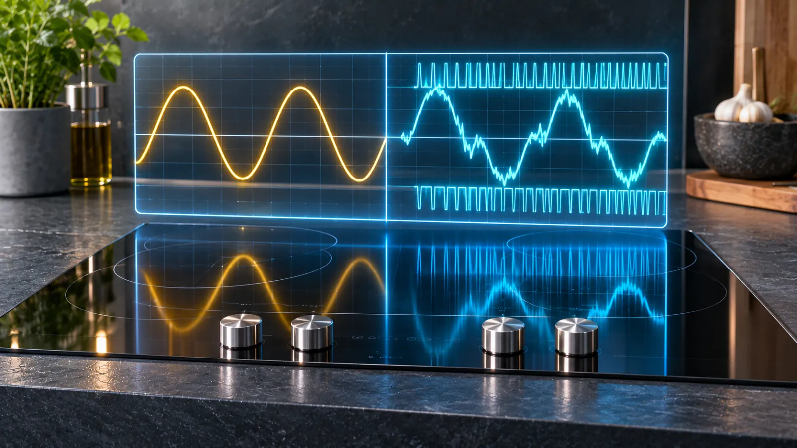
A kitchen hob is the largest single-phase load that most British households switch on and off by hand. Replacing a radiant ceramic hob with an induction hob cuts the energy needed to cook a given meal, because roughly 85% to 90% of the input power reaches the pan, against about 70% for a radiant element. It also changes the electrical character of the load in ways that a distribution network operator (DNO) cares about: the current is no longer a copy of the voltage, and a band of high-frequency noise appears that the older appliance never produced. This article audits that change from first principles, using circuit analysis, Fourier decomposition, capacitor sizing, filter behaviour and transformer loss models. Where a figure is a modelling assumption rather than a measured or published value, it is labelled as such.
1. Two loads, two physics
A radiant ceramic hob is as close to an ideal linear load as a domestic appliance gets. Each zone is a coiled or ribbon element of nickel-chromium alloy (typically 80/20 NiCr) behind a glass-ceramic plate. The element obeys Ohm’s law: a 2 kW zone on a 230 V supply has a hot resistance of V2/P = 2302/2000, about 26.5 ohms, and draws a current i(t) that is a scaled copy of the voltage. The power factor is 1.0, the displacement angle is zero and the current contains no harmonic content beyond whatever distortion was already present in the supply voltage. The element’s temperature coefficient of resistance is small, so the load does not change its own shape as it warms.
The ceramic hob is not electrically invisible, however. Power is regulated by an energy regulator, a bimetallic switch that cycles the element on and off with a duty ratio set by the dial. A 2 kW zone switching on and off every few seconds produces a step change in current of about 8.7 A, and therefore a small step in voltage across the supply impedance. Those steps are a voltage-fluctuation (flicker) issue, which is controlled by the IEC 61000-3-3 and 61000-3-11 families of standards and, on the network side, by Engineering Recommendation P28. They are not a harmonic issue. This distinction matters for the comparison: the ceramic hob has a flicker footprint and no harmonic footprint, while the induction hob has the reverse.
An induction hob is a power electronic converter with a coil on its output. The mains passes through an input filter and a single-phase diode bridge rectifier, producing a rectified DC link. A resonant inverter, built from one or two insulated-gate bipolar transistors (IGBTs), then drives a flat coil of roughly 50 to 100 microhenries inductance through a series or quasi-resonant capacitor. The coil’s alternating magnetic field induces eddy currents in the ferromagnetic base of the pan, and the pan base heats through its own resistance. When a pan is present, the coil’s equivalent inductance is lowered and the resonant frequency sits around 20 to 50 kHz. For example, an effective inductance of 60 microhenries with a 0.3 microfarad resonant capacitor gives f = 1/(2π√(LC)) of about 37.5 kHz. Power is controlled by moving the switching frequency relative to resonance, by changing the duty cycle, or, at low settings, by switching the whole inverter on and off.
Two topologies dominate. The half-bridge uses two IGBTs and splits the DC link, and is common on larger zones. The quasi-resonant (single-switch) design uses one IGBT and a parallel resonant capacitor, and is cheaper but places higher voltage stress on the device. Both share the same input stage, and it is that input stage, a bridge and a small capacitor, that sets the low-frequency harmonic behaviour seen by the supply.
2. Low-order harmonic generation and the small DC-link capacitor
A conventional switched-mode power supply uses a large electrolytic capacitor after the bridge to hold the DC voltage nearly constant. Because the capacitor only recharges when the mains voltage exceeds its own voltage, the current is drawn in narrow pulses near the voltage crest, and the harmonic content is severe: the third harmonic can reach 80% or more of the fundamental. An induction hob does not do this, and the reason is a matter of energy storage.
For a single-phase load drawing real power P at power factor 1, the instantaneous power is p(t) = P(1 − cos 2ωt), pulsating at twice the line frequency (100 Hz). To hold the DC link steady, a capacitor must absorb an energy swing of P/ω, which for a 2 kW zone is 2000/314, about 6.4 joules. Limiting the DC-link voltage ripple to 10% peak to peak on a 325 V link means (Vmax2 − Vmin2) of roughly 20,000 V2, so the required capacitance is 2 × 6.4/20,000, about 640 microfarads. An induction hob actually uses a film capacitor of a few microfarads, say 4.7 microfarads. At 325 V that stores only 0.5 × 4.7 × 10−6 × 3252 = 0.25 joules, which is about 124 microseconds of a 2 kW load out of a 10 ms half cycle. The capacitor is more than a hundred times too small to buffer the line. The DC-link voltage therefore follows the rectified sine wave, and the inverter simply draws whatever it needs from it. This is the design choice: by avoiding the large electrolytic capacitor and the active power factor correction stage it would otherwise require, the manufacturer saves cost, space and a lossy converter stage, and the input current stays far closer to a sine wave than a capacitor-input rectifier would produce.
It does not stay a perfect sine, because the inverter cannot operate near the zero crossings of the rectified voltage. When the DC link falls below the level needed to sustain resonant operation, the converter stops drawing current, and it resumes when the link voltage recovers. To a first approximation the current is a sine wave clipped at the start and end of each half cycle. Modelling the current as i(θ) = Ip sin θ for α < θ < π − α and zero elsewhere, the Fourier coefficients of the odd harmonics are
b1 = (Ip/π)(π − 2α + sin 2α)
bn = (2Ip/π)[ sin((n+1)α)/(n+1) − sin((n−1)α)/(n−1) ], for odd n ≥ 3
For an illustrative clip angle of α = 30 degrees (the inverter idle for the first and last sixth of each half cycle), the fundamental is 0.942 Ip and the harmonics relative to it are: 3rd (150 Hz) about 14.6%, 5th (250 Hz) about 14.6%, 7th (350 Hz) about 7.3%, 9th about 1.5%, 11th about 5.8% and 13th about 4.2%. The total harmonic distortion (THD) of the current is about 23%. Because the waveform is symmetric about the voltage crest, the displacement power factor stays at unity, and the true power factor is DPF/√(1 + THD2), about 0.975. The result is a clean illustration of the point: an induction hob can have a good displacement power factor and still inject a substantial third harmonic. Real hobs differ from the idealised clip because the input filter, the inverter control loop and the small capacitor all reshape the envelope. When the capacitor recharges near the crest and the inverter pulls current through the valley, the current can show the double-hump or “M” envelope that appears on measured traces, but the underlying spectral message is the same: odd harmonics, dominated by the third, fifth and seventh.
The IEC 61000-3-2 Class A limits for equipment drawing up to 16 A per phase are 2.30 A at the third harmonic, 1.14 A at the fifth, 0.77 A at the seventh, 0.40 A at the ninth, 0.33 A at the eleventh and 0.21 A at the thirteenth. A 2 kW zone draws about 8.7 A at the fundamental, so the modelled third harmonic is about 1.27 A, comfortably within the 2.30 A limit. At 16 A (about 3.7 kW) the modelled third harmonic rises to about 2.34 A, right at the limit, which explains why designers keep the clip angle and the filter characteristics tight. Hobs rated above 16 A per phase, which includes the common 7.4 kW (32 A) single-phase hob, fall outside IEC 61000-3-2 and are assessed under IEC 61000-3-12, which sets limits in terms of THD and partial weighted harmonic distortion as a function of the short-circuit ratio of the supply. The statement that a single unit “complies” is therefore correct, but the applicable standard depends on the rating.
3. DC-link ripple current and the part-load power factor collapse
The small DC-link capacitor does not merely shape the low-frequency current; it also carries the high-frequency ripple of the inverter. For a half-bridge inverter whose switch carries a half-sine pulse of peak Ipk in each switching cycle at 50% duty, the average current drawn from the link is Idc = Ipk/π and the RMS current is Ipk/2. The capacitor carries the difference between the pulsed current and its average:
IC,rms = √(Isw,rms2 − Idc2) = Ipk√(1/4 − 1/π2) ≈ 0.39 Ipk ≈ 1.2 Idc
At the crest of the mains cycle a 2 kW zone draws a mean DC current of about 7.8 A, so the capacitor carries roughly 9 A RMS of high-frequency ripple. With an equivalent series resistance of 10 to 15 milliohms, that is over a watt of heating inside a component that must survive tens of thousands of hours, which is one reason the capacitor has to be a film type rather than a small electrolytic. The ripple current in the capacitor is also the source of the high-frequency differential-mode current that the input filter must then suppress.
The input filter introduces its own problem at part load. To meet conducted-emission limits the hob includes X-class capacitors across the line, typically 1 to 2 microfarads in total, plus Y-class capacitors from line to earth. The X capacitors draw a reactive current regardless of the load: I = ωCV = 2π × 50 × 2 × 10−6 × 230, about 145 mA, which is a reactive power of about 33 VAr. At full power this is negligible. At a low simmer setting it is not. Induction hobs reach very low power in two ways: by shifting the switching frequency far above resonance, which is limited in range, and by burst firing, in which the inverter runs at a usable power for a few seconds and then stops, so that the average power is the duty ratio times the on-state power. This pulse-density modulation is efficient and reliable, but the filter capacitance is permanently connected, so the reactive component is constant while the real component falls. The true power factor is Pavg/√(Pavg2 + Q2) and, with Q = 33 VAr, it works out as follows: at 100 W average the power factor is about 0.95, at 40 W it is about 0.77, and at 30 W it falls to about 0.67. A 2 kW zone running at 2% duty simmering a sauce therefore presents a load of poor power factor even though it is drawing almost no power. The practical consequence for the network is small, because the currents involved are tiny, but the effect is real and visible in metering data; it also explains why the power factor stated on a datasheet is a full-load figure rather than a typical-use figure.
Burst firing has a second consequence. Switching a load of several kilowatts on and off every few seconds is a source of voltage fluctuation, and hobs usually synchronise their switching to the mains zero crossings to limit inrush and to avoid sub-harmonic content. When several zones cycle at different rates the resulting current envelope contains interharmonic components, and the flicker severity at the point of common coupling is assessed under the same rules that apply to the ceramic hob’s regulator.
4. Supraharmonic emissions, 2 kHz to 150 kHz
The band between 2 kHz and 150 kHz, called the supraharmonic range, sits in a regulatory gap. Harmonic standards such as IEC 61000-3-2 stop at the 40th harmonic (2 kHz), and the classical radio-frequency conducted-emission standards, CISPR 14-1 for household appliances, begin at 150 kHz. Between those limits there has been no mandatory emission limit for household appliances, although IEC 61000-2-2 has been amended to add compatibility levels for 2 to 150 kHz and IEC 61000-4-30 defines a measurement method that bins the band in 200 Hz steps.
An induction hob’s fundamental switching frequency, 20 to 50 kHz, lies in the middle of this band, and the inverter produces harmonics of that frequency as well. The voltage at the switch node is a rectangular wave, so its spectrum is a series of odd multiples of the switching frequency with amplitudes falling as 1/n. Those components appear as a high-frequency differential-mode current in the DC link and, through the parasitic capacitance between the switching devices, the coil and the chassis, as a common-mode current.
The input filter is meant to remove them, and it does so imperfectly in this band. A filter with a differential-mode inductance of 50 microhenries and X capacitance of 2 microfarads has a corner frequency of 1/(2π√(50 × 10−6 × 2 × 10−6)), about 16 kHz. A second-order filter attenuates at 40 dB per decade above the corner, so at 25 kHz the attenuation is only (25/16)2 ≈ 2.4 times, or about 8 dB. At 50 kHz it is about 20 dB. Because the filter was designed to meet limits that start at 150 kHz, where the attenuation is far greater, the supraharmonic band passes a significant fraction of the emission to the mains. That current flows into the household circuit and onward into the street network.
Three consequences follow. The first is interference with power line communication. Power-line-communication smart meters in much of continental Europe, using standards such as G3-PLC and PRIME, operate in the CENELEC A band of 3 to 95 kHz, exactly where hob emissions are strongest, and noise there raises the bit error rate. The qualification for Great Britain is important: the SMETS2 smart-meter system uses ZigBee within the home and cellular or long-range radio for the wide-area link, not power line carrier, so the direct exposure of British smart meters to this mechanism is smaller. PLC is still used for load control, street-lighting control and some utility telemetry, and static energy meters can show measurement errors under supraharmonic current, as laboratory studies have reported. The second is audible interference. Where two zones run at slightly different switching frequencies, the difference frequency can fall in the audible range: zones at 25.0 kHz and 25.8 kHz produce a beat at 800 Hz, which is why controllers synchronise adjacent zones. Neighbouring switch-mode power supplies and ferrite components can also rectify or mechanically respond to high-frequency ripple on the mains and produce an audible whine through magnetostriction. The third is nuisance operation of residual-current devices (RCDs).
The RCD problem arises through the Y capacitors and the coil’s parasitic capacitance to the pan and plate, which provide a path for high-frequency common-mode current to earth. The leakage current is I = 2πfCYVcm. With 2.2 nanofarads of Y capacitance, a common-mode voltage of 10 V at 30 kHz and a single appliance, the current is about 4 mA. That is well below a 30 mA trip threshold, but several appliances on a circuit add, and the 50 Hz leakage from the Y capacitors of other equipment adds again. A Type AC RCD responds only to sinusoidal residual current and a Type A device to sinusoidal and pulsating DC residual current; neither is designed for the high-frequency components that an inverter produces. A Type A device can be desensitised by high-frequency residual current, so that it fails to trip when it should, as well as tripping unnecessarily when leakage accumulates. Where a circuit carries inverter loads such as induction hobs, heat pumps or EV chargers, specifiers increasingly choose Type F or Type B devices, which are tested for composite and high-frequency residual currents.
5. Neighbourhood aggregation and transformer thermal derating
A single hob is a minor event. The network consequence comes from coincidence: between 5:30 PM and 7:00 PM a large proportion of homes on a feeder cook at once. To estimate how the currents combine, one must consider how harmonics of the same order add. IEC 61000-3-6 recommends a summation law, Ih = (Σ Ih,iα)1/α, with the exponent α equal to 1 for harmonic orders below 5, 1.4 for orders 5 to 10 and 2 for orders above 10. An exponent of 1 means arithmetic summation. For the third harmonic, which is generated with a fixed phase relationship to the fundamental by every hob of the same topology, the currents add essentially directly. This is the worst case for the low orders and it is the reason the third harmonic is the one to watch.
The three-phase four-wire layout of a UK low-voltage street makes it worse. The third harmonic and the other triplen harmonics (3rd, 9th, 15th) are zero-sequence: in each phase conductor they have the same phase angle, so they do not cancel in the neutral as the fundamental currents do when the load is balanced. They add arithmetically, and the neutral carries IN = 3 I3 if each phase has the same third-harmonic current I3. Take an illustrative feeder of 180 homes, 60 per phase, in which 40% of homes are cooking on induction at the evening peak, each drawing a mean of 1.5 kW. That is 36 kW per phase, or about 156 A of fundamental. If the modelled 14.6% third harmonic applies, each phase carries about 23 A of third harmonic, and the neutral carries about 68 A on top of whatever fundamental imbalance exists. If the neutral is already carrying 100 A of imbalance, the RMS neutral current becomes √(1002 + 682) = 121 A, and since heating scales with the square of current, the neutral conductor dissipates about 46% more power per metre. This is an illustrative case, not a measurement, but it shows why the neutral is the conductor most exposed to a growth in triplen content.
The same third-harmonic current produces a voltage distortion across the network impedance. A 500 kVA, 11 kV/400 V transformer with a 4.75% impedance has a reactance of about 15 milliohms at 50 Hz, or 46 milliohms at 150 Hz. For the zero-sequence third harmonic the return path through the neutral counts three times, so a street cable of 200 m of 185 mm2 aluminium (about 0.16 ohm per kilometre) adds roughly 33 milliohms in the phase and 33 milliohms in the neutral. The third-harmonic voltage at the end of the feeder is I3 × (Zphase + 3Zneutral) = 23 × (0.033 + 0.099), about 3 V, or about 1.3% of the 230 V supply, before adding the transformer reactance. For comparison, EN 50160 limits the third harmonic voltage to 5%, the fifth to 6% and the seventh to 5%, with total harmonic distortion limited to 8%. The figure here is a plausible upper bound at the feeder end, and it consumes a meaningful share of the headroom that Engineering Recommendation G5/5 reserves for all non-linear loads, not just hobs.
Inside the transformer, harmonic currents raise losses. Winding eddy-current loss scales with the square of both the harmonic current and the harmonic order: PEC ∝ Ih2h2. Define the harmonic loss factor FHL = Σ(Ih/I1)2h2 / Σ(Ih/I1)2. For the modelled hob spectrum, the numerator is 1 + 0.0213 × 9 + 0.0213 × 25 + 0.0053 × 49 + 0.0002 × 81 + 0.0034 × 121 + 0.0018 × 169, about 2.72, and the denominator is about 1.053, so FHL is about 2.6. The maximum permissible RMS load current in per-unit terms, following the approach of IEEE C57.110, is
Imax = √[ (1 + PEC-R) / (1 + FHL PEC-R) ]
where PEC-R is the rated eddy-current loss as a fraction of the I2R loss. For an assumed PEC-R of 0.08, a load made entirely of hobs with this spectrum gives Imax = √(1.08/1.206) = 0.946, a derating of about 5%. Real loads are a mixture, so the figure for a typical feeder is smaller; but the sensitivity is steep. If the weighted harmonic content were such that FHL reached 8, as it can when significant higher-order content from other converters is present, the permissible load falls to √(1.08/1.64) = 0.81, a derating of 19%. The point is not that the hob alone derates a transformer by 19%; it is that the margin is eroded by the sum of all non-linear loads, and the hob is a growing contributor at precisely the hour when the transformer is most heavily loaded.
The delta high-voltage winding of the standard Dyn11 distribution transformer provides a closed path in which zero-sequence third-harmonic flux is balanced by a circulating current. That keeps the triplen currents out of the 11 kV network, which is the intended behaviour, but it means the circulating current heats the delta winding and the extra zero-sequence flux induces stray losses in the tank and clamps. The heat is real, it simply remains inside the transformer.
6. The regulatory frame
Four layers apply. At the product level, IEC 61000-3-2 limits harmonic current for equipment up to 16 A per phase, with household appliances in Class A, and IEC 61000-3-12 covers equipment from 16 A to 75 A per phase. IEC 61000-3-3 and 61000-3-11 govern voltage fluctuation and flicker. At the network level, Engineering Recommendation G5/5 (published by the Energy Networks Association) sets planning levels for harmonic voltage distortion on UK networks and a staged assessment process for connecting non-linear equipment. Individual dwellings with type-tested appliances are generally treated as meeting the initial stage; the cumulative effect is what the planning levels are designed to manage. Engineering Recommendations P28 and P29 handle voltage fluctuation and voltage unbalance respectively, and the latter matters because a 7.4 kW single-phase hob is a large unbalanced load. At the supply-quality level, EN 50160 defines the voltage characteristics a customer can expect. At the supraharmonic level there is still no binding emission limit for household appliances in the 2 to 150 kHz band, only compatibility levels and measurement guidance, which is why it is the area where standards are least settled.
7. Comparative matrix
| Power Quality Parameter | Ceramic Radiant Hob (Linear Resistive) | Induction Hob (Resonant IGBT Inverter) |
|---|---|---|
| Load type and control | Nichrome element obeying Ohm’s law; power set by a bimetallic energy regulator cycling the element | Diode bridge, small film DC-link capacitor and half-bridge or quasi-resonant IGBT inverter driving a coil |
| Power factor at full load | 1.0 | About 0.95 to 0.98 (displacement near unity, reduced by distortion) |
| Power factor at low simmer | 1.0 when on | Falls towards 0.7 or lower as constant filter reactive power (about 33 VAr in the worked example) dominates a small real load |
| Current THD | Negligible | In the order of 20% to 25% in the clipped-sine model, with 3rd about 14.6%, 5th about 14.6% and 7th about 7.3% |
| Supraharmonic (2–150 kHz) emission | None | Significant at the 20–50 kHz switching frequency and its odd multiples; the input filter attenuates only about 8 dB at 25 kHz in the worked example |
| Dominant Circuit Mechanism | Resistive heating; on/off regulator produces current steps and flicker, not harmonics | The DC-link capacitor is over 100 times too small to buffer the line (about 5 µF against about 640 µF), so the current envelope follows the rectified sine and is clipped near zero crossings; high-frequency switching leaks past the filter |
| Household Circuit Impact | Low-frequency flicker from regulator cycling; no effect on RCDs or electronics | Cumulative Y-capacitor leakage and high-frequency residual current can cause Type AC or A RCD nuisance tripping or desensitisation; audible beats between zones and acoustic whine in nearby switch-mode supplies |
| UK DNO Transformer / Feeder Consequence | Voltage fluctuation under P28; otherwise a benign load | Triplen harmonics sum arithmetically in the four-wire neutral (neutral current of 3 × I3); eddy-current loss rises with Ih2h2, in the worked example derating a transformer by about 5% to 19%; delta winding carries circulating third-harmonic current |
| Efficiency to the pan | About 70% | About 85% to 90% |
| Governing standards | IEC 61000-3-3 and 61000-3-11; ER P28 | IEC 61000-3-2 (up to 16 A) or 61000-3-12 (16 to 75 A); ER G5/5; EN 50160; no binding supraharmonic limit |
8. What the audit means for each audience
For a DNO power quality engineer, the induction hob is not a crisis, and the audit does not show one. A single appliance meets its standard, the harmonic currents are modest in absolute terms, and the energy saved by the higher cooking efficiency is real. The concern is cumulative: the same evening peak that loads the transformer thermally also loads it harmonically, and induction hobs are joining heat pumps, EV chargers and inverter-driven appliances that all inject distortion in the same hours. The planning question is therefore how much of the G5/5 headroom is already committed, and monitoring that compares measured FHL and neutral current at the evening peak against the design assumptions is more informative than any single-appliance test.
For an electrical specifier, the practical controls are well understood. Balance single-phase hobs across phases to limit both fundamental imbalance and neutral current. Select RCDs suited to inverter loads, Type F or Type B where several inverter appliances share a circuit, and avoid placing many such loads behind one Type AC device. Check that the supply cable and neutral are sized for the growth in triplen current, not only the fundamental.
For a smart-grid architect, the supraharmonic band is the unsettled part. Communication systems that share the band, whether PLC meters elsewhere in Europe, street-lighting control or load-control signalling, need a measured noise floor rather than an assumption, and the measurement method in IEC 61000-4-30 gives a basis for it. The lack of a binding appliance limit below 150 kHz means any mitigation today comes from better filtering by the manufacturer or from the communication designer’s margin, not from a regulatory requirement.
For a clean-tech analyst, the balance of evidence is that induction is a net efficiency gain whose power-quality cost is real but manageable, provided the network’s harmonic headroom is monitored as electrification of heat, transport and cooking proceeds together. The physics that makes the induction hob cheap and efficient, a small DC-link capacitor and a high-frequency inverter, is the same physics that makes its current non-sinusoidal, and the engineering task is to account for that cost rather than to deny it.