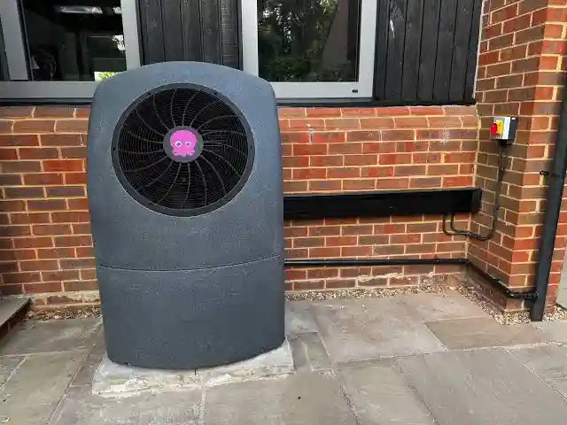
Heat pump quotations are conventionally built from a single number: the peak heat loss of the property at the local design temperature. That number selects the chassis, the chassis dictates the pipework, the pipework dictates the buffering strategy, and the output dictates the radiator schedule. Each step is a multiplier on cost. When the headline figure lands just above the capability of a compact unit, the specification tips into the next chassis up, and an entire cascade of additional capital expenditure follows. This article examines that cascade for the Octopus Cosy range, and explains the engineering logic of what can be called the Cosy 9 and 12 capital expenditure trick: lowering the design heat loss through targeted fabric work so that a property drops back into the smaller, single-fan chassis class. It is written for retrofit engineers, clean-energy property developers and independent heating system specifiers who need to test the claim against the physics before relying on it.
A note on sources is appropriate. Exact physical dimensions, fan counts, flow requirements and modulation ranges vary between product generations and should always be confirmed against the current manufacturer installation manual and MCS documentation. The figures in this article are derived from standard hydraulic and thermodynamic relationships, and illustrative values are labelled as such.
The Mechanical Physics of the Dual-Fan Chassis
An air-source heat pump extracts heat from outdoor air by passing it across a refrigerant-filled evaporator coil. The heat available is proportional to the mass flow of air and the temperature drop across the coil, so a larger rated output requires a larger air volume. The 6 kW class of unit achieves this with a single axial fan and a single evaporator face. The 9 kW and 12 kW classes need roughly half as much again, or twice, the airflow for the same coil temperature drop, and the manufacturer's response is a larger chassis with a bigger evaporator surface, and, in the models under discussion here, a dual-fan arrangement that spreads the airflow across a wider coil.
The physical consequences are measurable. The larger casing increases the footprint on the plinth or wall brackets, and it increases mass substantially, since the compressor, coil, heat exchanger, refrigerant charge and casing all scale. A heavier unit demands a firmer base: a concrete pad or a purpose-built frame on suitable ground, or wall brackets rated for a markedly higher static load plus dynamic loading from fan and compressor vibration. Mounting tolerances tighten accordingly. Installers should check the level of the base, the clearances for service access and the isolation of the unit from the structure with anti-vibration mounts. On a first-floor or wall-mounted installation, structural verification may be needed, which is a cost item that does not appear in a simple equipment quotation.
Acoustics scale in a nonlinear way. Fan noise rises steeply with tip speed, and two fans produce a higher sound power level than one, although each fan may run more slowly for a given airflow. The sound pressure at a neighbouring boundary also depends on the unit's position, the surrounding surfaces and the directivity of the discharge. Under the planning guidance that applies to permitted development, a heat pump must not exceed a specified sound level at the nearest habitable room of a neighbouring property, and the physical distance to the boundary rises with the unit's sound power. A larger dual-fan unit has fewer viable siting options, particularly in terraced or compact plots, and may need an acoustic enclosure or an alternative location, with the added pipework that entails.
Air recirculation is a further risk. A heat pump discharges air that is several degrees colder than ambient, and if that cold plume is drawn back into the intake, the evaporator sees a lower effective air temperature, the compressor works harder, the efficiency falls and frost formation accelerates. The larger the airflow, the greater the volume of cold air, the larger the plume and the more demanding the clearance requirements. Siting the unit in an alcove, between walls or near a fence can create a recirculation loop. A larger chassis requires larger clearances to the rear, the front and the sides, and it is more sensitive to prevailing wind direction. The specification therefore includes the siting survey as an engineering task, not an afterthought.
The Hidden Capital Expenditure Cascade
The dominant cost driver is not the chassis itself. It is the domino effect that a higher thermal output has on every downstream component. A heat pump delivers heat to a water circuit, and water carries heat in proportion to its flow rate and temperature rise, according to the relationship Q = ṁ × c × ΔT. Heat pumps are designed to operate with a flow-return difference of around 5 K to 7 K, much narrower than the 15 K to 20 K of a condensing boiler, because a low return temperature is not needed and a low flow temperature preserves efficiency. Narrow temperature differences demand high flow rates.
The arithmetic is straightforward. Taking the specific heat capacity of water as 4.19 kJ per kilogram per kelvin, the required flow rate in litres per minute is approximately the output in kilowatts multiplied by 14.3, divided by the temperature rise in kelvin. At a 5 K difference, a 6 kW output requires about 17 litres per minute, a 9 kW output about 26 litres per minute, and a 12 kW output about 34 litres per minute. At a 7 K difference the figures fall to about 12, 18 and 25 litres per minute. The jump from the smaller to the largest chassis therefore doubles the volumetric flow that the primary circuit must carry.
Pipe sizing follows from flow rate and acceptable velocity. Good practice keeps velocity at or below roughly 1.0 to 1.5 m/s in the primary circuit to control noise, erosion and pressure drop. A 22 mm copper pipe, with an internal bore of around 20 mm, carries roughly 20 to 28 litres per minute at those velocities, which suffices for a 6 kW class system and is marginal for a 9 kW class. A 28 mm pipe, with an internal bore of around 25 mm, carries around 30 to 45 litres per minute, which is the realistic minimum for a 12 kW system at a 5 K difference. The primary run between the heat pump and the cylinder or buffer, which in many properties is already installed in 22 mm or even 15 mm, may therefore need replacing wholesale. In a typical retrofit, that means lifting floors, opening ceilings and chasing walls, and the labour cost rapidly exceeds the cost of the copper.
Hydraulic separation compounds the issue. A larger heat pump needs a minimum water volume in the circuit to prevent short-cycling and to support defrost cycles, in which the unit temporarily reverses and extracts heat from the water to melt frost from the evaporator. Where the emitter circuit cannot supply that volume, a buffer vessel or low-loss header is specified. A buffer sized for a 12 kW unit is a large, heavy, insulated vessel that needs floor space, a dedicated support, additional pumps and valves, and extra insulation. Each of these components contributes to the bill of materials and to installation time, and the additional thermal losses and pumping energy slightly reduce the system efficiency.
The final element is the emitter schedule. Higher output does not by itself require larger radiators, since the radiators are sized to the room heat losses, not to the heat pump. But the designs that call for a 12 kW unit are by definition designs with high heat losses, and high heat losses must be matched by emitters with proportionally high output at the chosen low flow temperature. As the radiator formula demonstrates, a radiator's output at a mean water temperature of 45°C to 50°C is around 40 to 50 per cent of its nominal Delta T50 rating. A property with a 12 kW design heat loss will therefore need extensive upscaling of emitters in most rooms, often a mixture of Type 22 to Type 33 panels or fan-assisted convectors, along with the associated pipework alterations and decoration. The emitter budget in such a house can rival the cost of the heat pump itself.
Electrical infrastructure is the last link in the chain. A larger compressor has a higher start-up current and a larger running load, particularly in cold weather when the compressor is working hard and any backup heater may be active. The unit may require a larger circuit breaker, heavier cable, and a review of the property's maximum demand and incoming supply capacity. Where the existing consumer unit and cut-out are already near capacity, an upgrade, and potentially a DNO application, may be required. Even where a supply upgrade is unnecessary, the electrical load imposed by the larger unit should be assessed together with other new loads such as EV charging and electric cooking.
The Down-Sizing Strategy: Reducing Heat Loss to Shift the System Boundary
The cascade works in reverse. If the property's design heat loss falls, the heat pump required falls with it, and the savings propagate along the same chain: a smaller chassis, a smaller flow rate, a smaller pipe, a smaller buffer, fewer radiator changes and a smaller electrical load. The question is how much heat loss can be removed, at what cost, and what output range that releases.
The heat loss of a building at the design condition is the sum of fabric loss and ventilation loss. For each element, fabric loss is U × A × ΔT, where U is the thermal transmittance in watts per square metre kelvin, A is the area, and ΔT is the difference between the internal design temperature (usually 20°C to 21°C) and the external design temperature (commonly -3°C for much of England, with colder values in some regions). A representative design ΔT is therefore around 23 K. Ventilation loss is approximately 0.33 × n × V × ΔT, where n is the air change rate per hour and V is the volume in cubic metres.
Consider an illustrative example, with all figures indicative and not tied to a specific building. An uninsulated 1930s semi-detached house of about 110 square metres may have a design heat loss of around 9.5 kW to 10 kW. This would be flagged for a 9 kW or 12 kW class heat pump once a margin and hot water needs are added. Now apply the following measures:
- Loft insulation topped up to 270 mm or more: reducing the roof U-value from about 0.35 to about 0.14 W/m²K over a roof area of perhaps 55 square metres, at ΔT 23 K, saves approximately 0.27 kW. Where the loft was previously uninsulated, with a U-value of around 2.3, the saving is nearer 2.5 kW.
- Cavity wall injection: reducing the wall U-value from around 1.5 to around 0.5 W/m²K over a net wall area of perhaps 85 square metres, at ΔT 23 K, saves approximately 1.95 kW.
- Replacement of single glazing with advanced double or triple glazing: reducing window U-value from around 4.8 to around 1.4 W/m²K over perhaps 18 square metres, at ΔT 23 K, saves approximately 1.4 kW.
- Draughtproofing and controlled ventilation: reducing the infiltration rate from, say, 1.0 to 0.6 air changes per hour in a volume of about 275 cubic metres saves approximately 0.33 × 0.4 × 275 × 23, or around 0.83 kW.
Applied cumulatively to the uninsulated example, with the loft starting from a poor baseline, these measures remove in the region of 3 kW to 4 kW from the design heat loss, taking a notional 9.5 kW requirement down to between 5.5 kW and 6.5 kW. That value sits within the capability of a 6 kW class unit on the design day, and the system boundary has shifted from the dual-fan class to the single-fan class. The exact threshold should be confirmed from the manufacturer's published output at the design external and flow temperatures, because a nominal rating is quoted at a specific test condition, usually milder than the design day, and the output of any air-source unit falls as the outdoor temperature falls.
The cumulative effect is not strictly additive, since the improvements interact (the saving from a better wall depends on the other losses in the room), and a room-by-room recalculation under the MCS method or an equivalent standard is essential. But the order of magnitude is representative. It is also important to note that the savings apply on every cold day throughout the heating season, not just the design day, so the same intervention reduces the annual energy demand and hence running costs for any heating system, with or without a heat pump.
The financial logic then reduces to a comparison of marginal costs. On one side is the cost of the fabric measures. On the other is the avoided cost of the larger heat pump, the replacement of primary pipework, the buffer vessel, the additional emitter upgrades, and any electrical reinforcement, plus the ongoing benefit of lower running costs. In houses with poor fabric and straightforward access, the avoided costs often exceed the cost of the measures, and the fabric work is effectively subsidised by the heating system budget. In houses where the fabric is already good, or where the measures are difficult or expensive, such as solid walls or listed buildings, the trade-off is less favourable, and the larger unit may be the right choice. This is a calculation, not a doctrine.
Seasonal Efficiency: Modulation and Short-Cycling
The second argument for down-sizing concerns efficiency in operation, and it rests on the way a variable-speed heat pump behaves across the heating season. The design day, the coldest day for which the system is sized, occurs only a handful of times in an average winter. For most of the season, the heating demand is a fraction of the peak, often 30 to 60 per cent. A heat pump must match its output to that lower demand, and it does so by modulating the compressor speed down to a minimum output, usually between 20 and 40 per cent of the maximum output at a given condition, depending on the design.
When the demand falls below the minimum modulation output, the heat pump can no longer match it continuously, and must cycle on and off. Each start-up involves a period of inefficient operation as the refrigerant pressures equalise and the compressor accelerates, and each shutdown loses heat from the system. Frequent short cycles increase the mechanical wear on the compressor, reduce the average COP, and can produce uneven comfort with noticeable temperature swings. An oversized unit reaches this lower bound sooner, and spends a larger fraction of the season in the cycling regime, particularly during the milder shoulder months of autumn and spring.
A smaller unit, correctly sized to the improved building, operates differently. In the shoulder months, its minimum output is closer to the building's actual demand, so it can run continuously at low speed, which is where compressor efficiency is typically highest. During colder weather it operates closer to its maximum modulation ceiling and is working at its design condition, but the continuous operation avoids the transient losses of cycling. Run time at a stable low flow temperature, driven by weather compensation, produces a higher seasonal performance factor (SPF), and the difference between a well-matched and a poorly matched unit can be a few tenths of a point of SPF, which is significant over many years of operation.
Flow temperature interacts with this. A smaller heat pump serving a better-insulated building typically runs a lower weather-compensated flow temperature for the same room emitters, because the emitters now have surplus capacity relative to the reduced demand. Each degree of flow temperature reduction improves the COP by a few per cent, so the fabric work yields a double benefit: less heat required, and a more efficient way of delivering what remains. The practical result is lower electricity consumption, a lower peak load on the supply, and a more stable indoor temperature.
The counterargument deserves a fair statement. An undersized unit that cannot meet the design day will rely on its backup immersion heater, which runs at a COP of one, and the resulting electricity cost is severe. It is therefore essential to size the down-sized system against a verified heat loss calculation for the post-works building, with a defined margin, and to ensure that the fabric measures are actually completed before the heat pump is specified at the lower capacity. Commissioning the smaller system in a house where the insulation works have been delayed is a recognised failure mode.
The Comparative Matrix
The matrix below compares the three chassis classes on the parameters that drive downstream cost. Flow rates are calculated at a 5 K flow-return difference from the relationship Q = ṁ × c × ΔT, and pipe recommendations assume a velocity of roughly 1.0 to 1.5 m/s. Confirm the minimum flow rate and connection sizes against the current manufacturer documentation for each model.
| Cosy Chassis Model Variant | Compressor & Fan Configuration | Design Peak Output Ceiling | Minimum Volumetric Flow Requirement | Typical Primary Pipe Bore Requirement |
|---|---|---|---|---|
| Cosy 6 | Variable-speed compressor with a single-fan chassis | Approximately 6 kW | Approximately 17 litres per minute at a 5 K difference | 22 mm copper, and 15 mm only for short runs at the lower end of the range |
| Cosy 9 | Variable-speed compressor with a dual-fan chassis | Approximately 9 kW | Approximately 26 litres per minute at a 5 K difference | 22 mm copper at the limit of velocity, with 28 mm preferred for longer runs |
| Cosy 12 | Variable-speed compressor with a dual-fan chassis | Approximately 12 kW | Approximately 34 litres per minute at a 5 K difference | 28 mm copper throughout the primary circuit, with a buffer or low-loss header |
Engineering Verdict and Specification Guidance
The analysis supports a clear but conditional conclusion. A 9 kW or 12 kW specification is not merely a larger heat pump. It is a different class of project, with a larger footprint, a higher acoustic and structural burden, a doubled flow requirement, heavier pipework, buffering and emitter work, and a bigger electrical load. Where a property sits close to the boundary between chassis classes, targeted fabric improvements can shift it across that boundary and unlock a cascade of savings. The following approach is recommended for specifiers:
- Calculate heat loss room by room before selecting a chassis. Use measured dimensions and verified U-values, and do not rely on floor-area rules of thumb or the previous boiler's rating.
- Quantify the distance to the boundary. If the design heat loss sits within 3 kW to 4 kW of the next lower class, price the fabric measures that could close the gap.
- Cost the whole cascade. Compare the total installed cost of each pathway, including primary pipework, buffer volume, emitter upgrades, electrical works and structural mounting, not just the equipment price.
- Sequence the work correctly. Complete fabric measures before commissioning, and size the heat pump to the improved building with a documented margin.
- Verify output at the design condition. Use the manufacturer's performance data at the local design external temperature and the planned flow temperature, not the headline nominal rating.
- Retain the larger unit where the fabric cannot be improved. For solid-walled or protected properties where measures are costly or impossible, accept the larger chassis and design the hydraulics properly.
- Survey the siting. Check clearances, acoustic compliance, structural support and recirculation risk for whichever chassis is chosen.
In summary, the supposed trap of the dual-fan chassis is really an asset-optimisation problem about where the system boundary is drawn. A specifier who treats the heat loss as a fixed input will buy the larger machine and pay for everything that follows. A specifier who treats the heat loss as a design variable can often buy a smaller machine, a lighter hydraulic system and a more efficient season, at a total cost that is lower and a running performance that is better. The decision should be driven by localised calculation, standardised method and verified data, rather than by the size of the number on the first quotation.