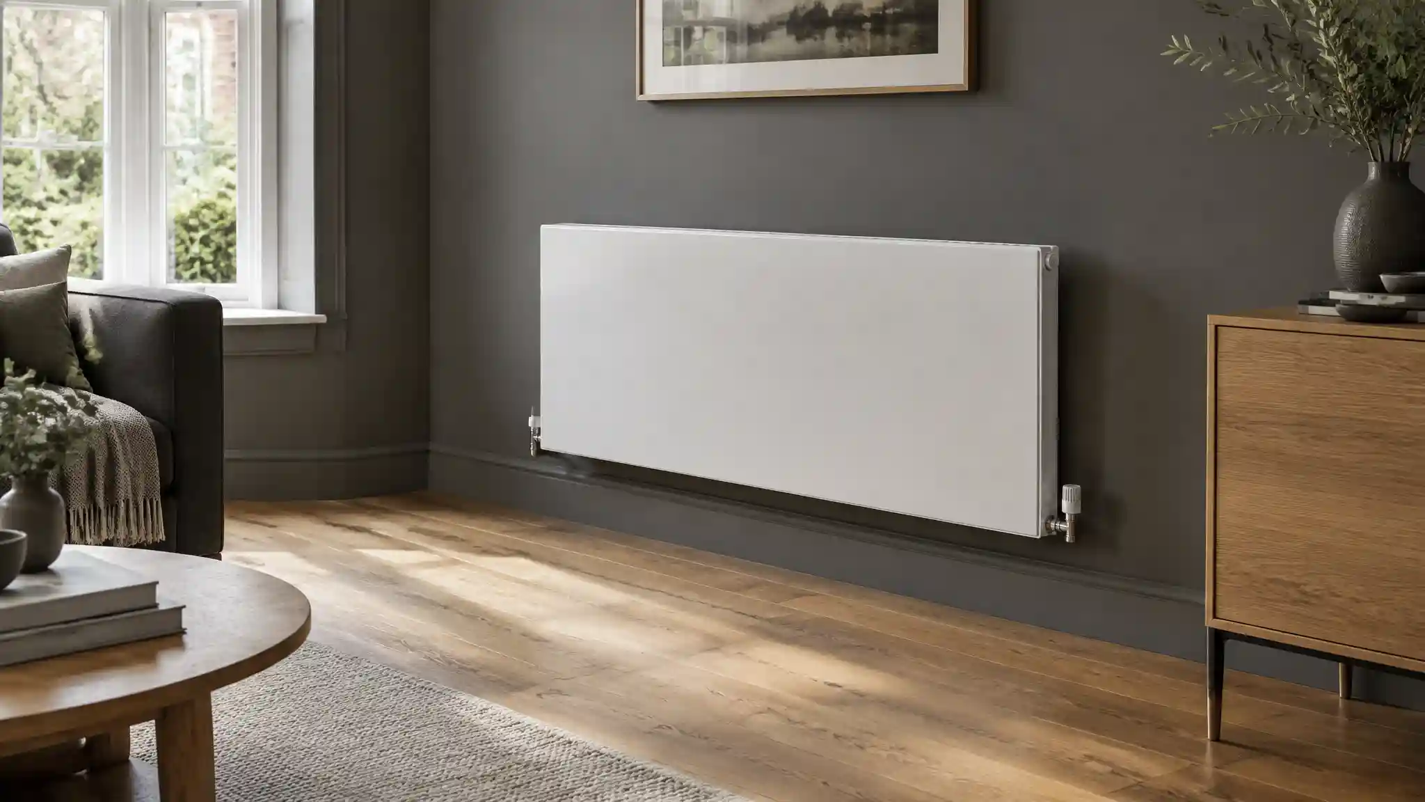
Few topics in heat pump retrofit generate as much avoidable expense as radiator sizing. The prevailing assumption, that every emitter in a gas-boiler house must be ripped out and replaced before a heat pump can operate, is frequently wrong, but the opposite assumption, that nothing needs to change, is equally unsafe. The correct answer is always a room-by-room calculation, and that calculation rests on one variable, the temperature difference between the water in the radiator and the air in the room, universally expressed as Delta T. This article deconstructs the mathematics, the fluid mechanics, the effect of emitter geometry and the interaction with the building fabric, so that building services engineers, retrofit coordinators and heating system specifiers can characterise each emitter on evidence rather than on rule of thumb.
Defining Delta T: The Mathematics of Mean Water Temperature
Radiator manufacturers publish nominal outputs against a standardised test condition. Under BS EN 442, the reference is Delta T50: a mean water temperature (MWT) 50 K above the surrounding air temperature, with the room at 20°C. Mean water temperature is the arithmetic average of the flow and return temperatures. A traditional gas boiler design of 75°C flow and 65°C return gives an MWT of 70°C. Subtract the 20°C room temperature and the result is 50 K, hence Delta T50. Every catalogue output, whether stated in watts or British thermal units, is quoted at this point unless stated otherwise.
The difficulty arises because a heat pump does not operate efficiently at these temperatures. The coefficient of performance (COP) falls as the difference between the source temperature and the delivery temperature widens, so an air-source heat pump prefers to run with the lowest flow temperature that still satisfies the building. A design of 55°C flow and 45°C return gives an MWT of 50°C and a Delta T of 30 K, the usual definition of Delta T30. A more ambitious design of 45°C flow and 40°C return gives an MWT of 42.5°C, and therefore a Delta T of 22.5 K. Note that the label "Delta T30" refers to the temperature difference between water and room, not to the flow-return difference. This is a frequent source of confusion on site, particularly because heat pumps are typically designed around a flow-return difference of 5 K to 10 K, far narrower than the 10 K to 20 K of a condensing boiler.
The relationship between output and Delta T is not linear. A radiator loses heat by a combination of convection and radiation, and the convective component is itself a nonlinear function of temperature difference, because the buoyancy-driven airflow over the panel strengthens as the surface becomes hotter. The standard empirical model expresses the output as the nominal output multiplied by the ratio of actual to reference Delta T, raised to a power known as the radiator exponent, n:
Q = Q50 × (ΔT / 50)n
For typical steel panel radiators the exponent is about 1.3, with published values for individual models usually lying between 1.2 and 1.4 and higher for some finned convectors. Because the exponent exceeds one, the output falls faster than the temperature difference does. Taking n as 1.3, the correction factors are as follows. At Delta T40 the output is about 75 per cent of nominal. At Delta T30 it is about 51 per cent. At Delta T25 it is about 41 per cent. At Delta T22.5 it is about 35 per cent. In other words, a radiator rated at 1,000 W at Delta T50 delivers only around 510 W at Delta T30, and only around 350 W at a 45°C flow and 40°C return. This is the mathematical heart of the matter: halving the temperature difference does not halve the output, it cuts it by rather more than half.
The inverse figure is the one used for sizing. To deliver the same heat from the same room, the surface area, or the effective output rating, must be multiplied by the reciprocal of the correction factor: about 1.34 at Delta T40, about 1.94 at Delta T30, about 2.46 at Delta T25, and about 2.83 at Delta T22.5. A radiator that exactly meets the design heat loss of a room at Delta T50 would therefore need to be nearly twice the size at Delta T30 if the room's heat demand were unchanged. This explains why a naïve like-for-like swap is so often inadequate, and also why many engineers jump to the assumption that all emitters must be replaced. The remaining sections explain why that conclusion is often premature.
Fluid Thermodynamics and the Flow-Rate Penalty
Reducing the temperature does not only shrink the output per square metre. It changes the hydraulics. The heat carried by a water circuit is governed by Q = ṁ × c × ΔT, where ṁ is the mass flow rate, c is the specific heat capacity of water (about 4.19 kJ per kilogram per kelvin) and ΔT here is the flow-return difference. A boiler circuit with a 20 K difference carrying 1 kW needs roughly 0.7 litres of water per minute. A heat pump circuit with a 5 K difference needs roughly 2.9 litres per minute for the same 1 kW, and with a 10 K difference it needs about 1.4 litres per minute. Across a whole house, a heat pump system must typically move three to four times the volume of water that a boiler system would for the same output.
That volume has to pass through the existing pipework. Fluid velocity rises in proportion to flow rate for a given bore, and pressure drop rises roughly with the square of velocity. Legacy installations with 8 mm or 10 mm microbore runs can reach velocities that produce noise, erosion and prohibitive pump head, while 15 mm and 22 mm copper generally copes comfortably. As a general design guide, velocities in the order of 1.0 m/s or below are preferred, and primary circuits of 28 mm or larger may be required where the heat pump is rated at higher outputs. Specialised hydraulic balancing, the use of a low-loss header or buffer, and variable-speed circulators form part of an appropriate design, but pipework restrictions are often the real limit on retaining existing emitters, not the radiators themselves.
There is a second hydraulic effect that couples to emitter performance. Lowering the flow-return difference means the radiator surface is closer to a uniform temperature, because the water has less opportunity to cool as it passes through. That slightly improves the mean surface temperature for a given MWT and tends to produce a more even heat distribution across the panel. The effect is real but modest, and does not change the underlying sizing logic. What matters is that the MWT is controlled correctly and that every emitter is balanced, since a poorly balanced system will starve distant radiators of flow and force the heat pump to raise its flow temperature to compensate, which degrades the efficiency that the larger emitters were installed to protect.
Low-flow operation also interacts with the control strategy. Weather compensation modulates the flow temperature according to outdoor temperature, so that the system delivers only the temperature the building needs on a given day. Most of the heating season occurs at milder outdoor conditions than the design day, so the emitter is oversized for much of the year and the heat pump can run continuously at low flow temperatures. This is the core principle of a well-designed system: size the emitters so that the design-day demand can be met at the target low flow temperature, then let weather compensation exploit that margin for the rest of the year. Continuous, low-temperature operation avoids the short-cycling that occurs when an undersized emitter forces cycling on and off, with consequent wear and reduced seasonal efficiency.
Emitter Surface Area: Type 11, Type 22 and Type 33
The compensating variable is surface area. A panel radiator is described by a type code that identifies the number of water panels and convector fins. A Type 11 is a single panel with a single convector, a Type 21 has a double panel and a single convector, a Type 22 is a double panel with double convectors, and a Type 33 is a triple panel with triple convectors. Each additional panel or fin layer increases the heat-emitting surface area and the convective airflow for the same wall footprint. Although the exact figures vary between manufacturers, a Type 22 typically delivers roughly 1.6 to 1.8 times the output of a Type 11 of identical height and length, and a Type 33 typically delivers roughly 2.2 to 2.4 times.
These ratios are what make a retrofit practicable. A Type 11 radiator in a room can be upgraded to a Type 22 of the same height and length, using the same wall brackets and a similar pipe position, providing about 1.7 times the output with no change to the room layout and only a modest increase in depth, typically 30 mm to 50 mm. For a Delta T30 design, where a factor of about 1.9 is required, upgrading from Type 11 to Type 22 and increasing the length modestly will often close the gap. Where a Type 22 is already installed, moving to a Type 33 may supply the additional factor. Where wall space is constrained, deeper-profile emitters, taller panels, towel-rail-style vertical designs, or specialised fan-assisted convectors (which raise the effective exponent and reduce the size penalty by forcing airflow) can fill the gap. Underfloor heating, with a large surface area and typical flow temperatures of 35°C to 45°C, is the other ideal partner for a heat pump, but it is rarely practicable as a retrofit in an existing building.
Several practical checks accompany this exercise. Wall space and clearance must allow the deeper panel without obstructing furniture or doors. Pipe centres should be checked, since replacing a radiator with another of different connection spacing may require alterations to the pipework. Pipe sizes must be compatible with the new flow rates, as discussed above. The radiator's exponent should be taken from the manufacturer's data rather than assumed, as differences between models change the correction factor by several percentage points. And the target room temperature must be verified, since the design temperatures differ by room: living areas at 21°C, bedrooms at 18°C, bathrooms at 22°C, and so on. Each degree changes the Delta T and therefore the output.
The Fabric-First Interaction
The sizing equation has two sides. Everything above concerns the supply of heat from the emitter. The demand side is the room's heat loss, expressed in watts, which depends on the temperature difference between inside and outside and on the fabric through which the heat escapes. Calculated by the standard method for each room, heat loss is the sum of fabric losses (U-value multiplied by area multiplied by temperature difference for each wall, window, floor and roof) and ventilation losses (based on air change rate and volume). Improving the fabric lowers the required watts, and since the required output sits on the demand side of the equation, a lower demand reduces the surface area needed to meet it.
The effect can be dramatic. Replacing single glazing, with a U-value near 4.8 W/m²K, with modern double glazing near 1.4 W/m²K cuts window heat loss by roughly 70 per cent. Raising loft insulation from 100 mm to 270 mm or more reduces the roof U-value from around 0.35 W/m²K to about 0.14 W/m²K. Filling cavity walls reduces the wall U-value from around 1.5 W/m²K to around 0.5 W/m²K. Draughtproofing reduces the ventilation component. Together, such measures can reduce a typical older house's peak heat loss by a third or more. A room requiring 1,500 W at the original design condition might require only 900 W after upgrades, and if the existing radiator can deliver 900 W at Delta T30, it passes without replacement. In practice, the existing emitter capacity at Delta T50 is often substantially larger than the demand because radiators were routinely oversized relative to the original heat loss, so there is frequently additional headroom as well.
The correct workflow therefore proceeds in a specific order:
- Calculate room-by-room heat loss using measured dimensions, actual or reasonably estimated U-values, and the local design outdoor temperature, both for the current fabric and for any planned improvements.
- Identify the installed emitter in each room, recording type, height, length and manufacturer, and obtain its nominal output and exponent.
- Calculate the output at the target mean water temperature using the correction formula above.
- Compare output with demand and classify each room as sufficient, marginal or deficient.
- Prioritise upgrades to the deficient rooms, typically a small subset, choosing the minimum change that closes the gap, such as a Type 11 to Type 22 swap or a longer panel.
- Verify the hydraulics, checking pipe sizes, flow rates and balancing, and commission with weather compensation enabled.
It is also worth stating the limits of the argument. Fabric measures are not always possible or economic, particularly in solid-walled or listed properties, and they should not be assumed. Where fabric improvements are planned, the heat pump should be sized to the improved building, not to the one that currently exists, and the timing of the works must be coordinated so that the system is not commissioned undersized before the improvements land. Where improvements are not planned, the radiator schedule must be built from the existing heat loss. In both cases the principle is the same: the emitter and the building are a single system, and optimising one without the other forfeits the largest available saving.
Coefficient of Performance and the Economics of the Trade-Off
The motivation for all of this is efficiency. A rule of thumb widely used by installers is that each 1 K reduction in flow temperature improves the heat pump's COP by roughly 2 to 3 per cent, though the exact figure depends on the unit, the outdoor temperature and the compressor's operating point. Moving from a 70°C flow to a 55°C flow, then to 45°C, can therefore lift the seasonal COP from the high twos towards or above four in a well-designed installation. The financial effect scales with consumption: on a typical annual heat demand, a seasonal COP improvement of 0.5 can save hundreds of pounds a year in electricity, and the payback on a modest emitter upgrade is correspondingly attractive.
The relationship is subject to diminishing returns, however. Each reduction in the design flow temperature requires a larger increment of radiator surface area than the last, as the correction factors above demonstrate: moving from Delta T30 to Delta T22.5 demands about 46 per cent more surface area for the same output, while the COP gain is a few percentage points per kelvin. There is an optimum, and it differs by building. In a well-insulated house with generous existing emitters, a very low flow temperature may be achieved at small cost. In a poorly insulated house with undersized radiators, the cost of reaching Delta T22.5 may exceed the lifetime value of the efficiency gain, and a compromise design at Delta T30 to Delta T35, perhaps with selective upgrades, is the rational choice. Asset-optimisation in this context means finding the point at which the marginal cost of additional emitter area equals the marginal value of the improved COP, not pursuing the lowest possible temperature as a goal in itself.
The Comparative Matrix
The matrix below compares the principal design baselines. Correction factors assume a radiator exponent of 1.3 and a room temperature of 20°C. COP impacts are indicative, vary by unit and climate, and should be confirmed using the manufacturer's performance data.
| Design Temperature Baseline | Mean Water Temperature (MWT) | Relative Heat Output Percentage | Radiator Surface Area Factor | System Coefficient of Performance (COP) Impact |
|---|---|---|---|---|
| Delta T50 (75°C flow / 65°C return) | 70°C | 100% | 1.0 (reference) | Poor: high lift, heat pump COP typically near or below 2.5 |
| Delta T40 (65°C flow / 55°C return) | 60°C | Approximately 75% | Approximately 1.34 | Modest: acceptable for hybrid or transitional systems |
| Delta T30 (55°C flow / 45°C return) | 50°C | Approximately 51% | Approximately 1.94 | Good: typical seasonal COP in the region of 3.0 to 3.5 |
| Delta T25 (50°C flow / 40°C return) | 45°C | Approximately 41% | Approximately 2.46 | Very good: seasonal COP commonly 3.5 to 4.0 |
| Delta T22.5 (45°C flow / 40°C return) | 42.5°C | Approximately 35% | Approximately 2.83 | Excellent: seasonal COP of 4.0 or more, but the emitter cost rises steeply |
Engineering Verdict and Specification Guidance
The evidence supports a measured conclusion. The mathematics is unambiguous: lowering the mean water temperature reduces radiator output faster than the temperature difference falls, and the surface area must rise accordingly. But the demand side of the equation is equally real, and a fabric-first approach combined with room-by-room analysis typically reveals that most of a property's existing radiators are adequate or can be made adequate with minimal modification. The following guidance summarises the recommended approach for specifiers:
- Never size from a rule of thumb. Calculate heat loss and emitter output for each room, using manufacturer exponents and actual dimensions.
- Treat Delta T30 as the practical target. It offers the best balance of efficiency and emitter cost for most existing buildings, with lower targets reserved for well-insulated properties.
- Upgrade selectively. Convert Type 11 to Type 22 or increase panel length only in rooms where the calculation shows a deficit.
- Verify the pipework and hydraulics. Confirm that bore sizes, pump head and balancing can sustain the higher flow rates, particularly on legacy microbore circuits.
- Coordinate fabric works with heat pump sizing. Size the system to the improved building where upgrades are committed, and avoid commissioning ahead of them.
- Commission with weather compensation. Let the control strategy exploit the oversized emitter margin on the milder days that make up most of the heating season.
In summary, radiator sizing for a heat pump is a localised, quantifiable engineering exercise, not an automatic replacement programme. The specifiers who deliver the best outcomes are those who characterise each room accurately, retain what the numbers permit, and invest only where the deficit is demonstrated. That is asset-optimisation in its most practical sense: a standardised method, applied rigorously, that protects both the efficiency of the heat pump and the budget of the client.