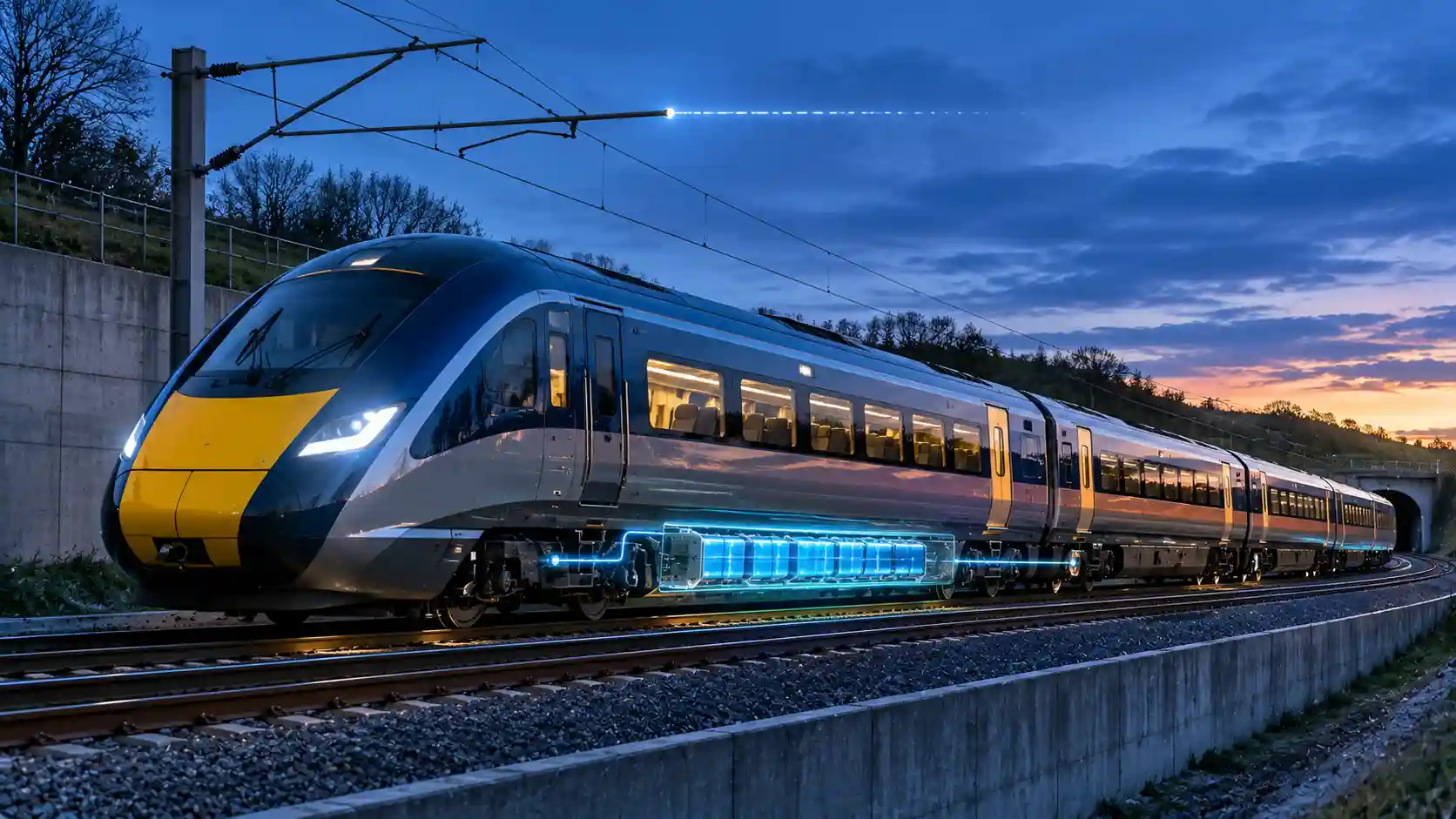
Britain’s railway has spent two decades arguing about wires. Only around 39 per cent of the national network is electrified, and the remaining 61 per cent is worked by diesel multiple units, bi-mode intercity sets and freight locomotives that burn fossil fuel under the shadow of a decarbonisation target that has not moved. The conventional answer, continuous 25kV AC overhead line equipment (OHLE) on every route, has been tested by the Great Western, Midland Main Line and TransPennine programmes and found to be expensive, slow and prone to cost escalation wherever the infrastructure is old. Great British Railways (GBR) is now steering towards a different engineering premise: electrify the trunk, store energy on the train, and let the vehicle cross the gaps. This article audits that premise from the pantograph to the substation, and from the traction pack to the procurement spreadsheet.
The analysis below separates three things that are often conflated in public debate: the vehicle technology (battery-electric multiple units, or BEMUs, and tri-mode units), the infrastructure strategy (discontinuous electrification and station-based charging), and the fleet-standardisation framework that determines which vehicle goes where. Figures quoted from procurement announcements are attributed as reported; figures marked as indicative are first-order engineering estimates that readers should replace with their own route data before using them in a business case.
Why Continuous Electrification Hit a Cost Wall
The capital cost of OHLE is dominated not by masts and wire but by everything the wire collides with. A plain-line electrification scheme across open country has historically been delivered at roughly £1 million to £2.5 million per single-track kilometre (indicative, depending on era, scale and contractor learning), whereas a scheme threading through cuttings, overbridges, tunnels and listed viaducts can multiply that figure several times over. The reason is geometric. A 25kV AC system requires a minimum clearance between live conductor and earthed structure, set by the dielectric strength of air and by the pollution and weather margins specified in the applicable standards. Where an overbridge soffit is too low, the options are to reconstruct the bridge, to lower the track, to fit insulated barriers and reduce the permissible clearance (with the associated speed and maintenance consequences), or to give up.
Track lowering is itself a major intervention. The ballast or slab must be excavated, drainage re-engineered, signalling cabling re-routed and, in tunnels, the invert re-profiled while the structure remains stable. Each of those operations demands possession time, and each possession compresses the available maintenance window on a network already running close to capacity. The result is the familiar pattern of programmes that begin with a headline price per kilometre and finish with a very different figure once the structures survey is complete. A strategy that avoids the worst 10 per cent of structures can therefore remove far more than 10 per cent of the cost.
This is the economic logic that discontinuous electrification exploits. Instead of wiring every metre, the infrastructure manager wires the sections where wire is cheap and where train density justifies it, typically the high-frequency trunk, the approaches to major stations and the heavily graded sections where traction power is highest. The sections that are expensive to wire, lightly used or both are left bare, and the train carries enough stored energy to cross them.
The Physics of Discontinuous Electrification
Pantograph drop-and-raise cycles at line speed
In a discontinuous scheme the train must transition between powered and unpowered modes without the driver stopping and without a service-affecting interruption. The sequence begins before the end of the wired section. A trackside balise or an on-board route database triggers the traction control system to shift the power source: the main circuit breaker opens under controlled current, the traction converter’s DC link is re-supplied from the battery through a DC/DC stage, and the pantograph is lowered. Automatic dropper devices (ADDs) and lineside signage remain the safety backstop that guarantees the pantograph is down before the wire ends, protecting against a raised collector striking a termination structure.
The reverse cycle is more demanding. As the train approaches a wired section at speed, the pantograph must be raised against aerodynamic loads, make contact with the contact wire within a defined transition zone, and stabilise its contact force before the main circuit breaker closes and the transformer is energised. Modern pantographs are designed to raise in a few seconds, and the contact-wire profile at the entry to a wired section is graded so that the collector rises into a gently tapered approach and not into a sudden step. The control logic cross-checks line voltage, phase and pantograph height before closing the breaker. Tolerances here are tight: a mistimed raise produces arcing at the contact strip, which accelerates carbon wear and radiates electromagnetic interference into track circuits and axle counters.
The infrastructure-side implication is that discontinuous electrification is not simply ‘wire with gaps’. It requires engineered transition zones: defined raise and lower points, gradual contact-wire height changes, neutral or earthed terminations at the wire ends, and clear driver and system cues so that the sequence is repeatable across hundreds of train movements a day. Where the sequence is automated and properly proven, the dwell cost of the transition is effectively zero; where it is not, it becomes a source of delay minutes that erodes the business case.
Traction packs and the energy budget
The battery is sized from the route, not the other way round. Consider an indicative three-car regional BEMU with a traction energy consumption of around 2.5 kWh per vehicle-kilometre on a typical branch line with stops every five to eight kilometres. The train therefore needs about 7.5 kWh per kilometre. A 50-mile (approximately 80 km) unwired excursion consumes some 600 kWh. Batteries are not run from 100 per cent to zero: operators typically limit the usable window to something like 70 to 80 per cent of nominal capacity in order to protect cycle life, and they add a reserve for diversion, heating, delay and end-of-life capacity fade. Working back through those margins gives a nominal pack of roughly 1.0 to 1.4 MWh for a 50-mile reliable bound. Longer bounds, higher-speed operations and winter heating loads push the figure into the multi-megawatt-hour range.
Mass is the binding constraint. At a pack-level energy density in the region of 120 to 160 Wh per kilogram (including cooling, enclosure and battery-management hardware), a 1.2 MWh pack weighs somewhere between 7.5 and 10 tonnes. That mass must be mounted in the underframe space beneath the floor, within the vehicle gauge, and distributed so that axle loads remain within the limits set by the infrastructure manager. Underfloor mounting also demands thermal management: liquid-cooled plates or forced-air systems hold cell temperature inside the narrow window in which lithium-ion chemistry delivers both power and longevity. Sodium-ion cells, with lower energy density but better low-temperature behaviour, cheaper raw materials and a favourable safety profile, are a credible alternative for rail duty where volume is less critical than lifetime cost, a point developed in our analysis of stationary storage chemistries.
Cycle life matters as much as capacity. A branch-line BEMU may complete a deep discharge cycle several times a day, which implies something like 1,500 to 2,500 equivalent full cycles a year. Over a 30-year vehicle life that is far beyond the warranted life of any single pack, so the commercial model must anticipate at least one mid-life pack replacement. Procurement frameworks that treat the battery as a leased or exchangeable module, and not as a permanently fitted structural component, tend to preserve value as cell prices fall.
Regenerative braking as an energy source
Regeneration is where a battery train earns part of its range back. A 150-tonne unit travelling at 100 mph (about 44.7 metres per second) carries roughly 150 megajoules of kinetic energy, equivalent to some 42 kWh. On a line with frequent stops from lower speeds, the energy per stop is smaller, but the recoverable fraction is applied many times a day. During braking, the traction motors operate as generators, delivering several megawatts at peak, and the converter feeds the power back to the DC link. On an OHLE-fed train that surplus can be returned to the contact wire if another train or substation can accept it; on a battery train the surplus is absorbed by the pack, subject to the battery’s charge acceptance limits.
In practice, round-trip recovery to the pack is well below the theoretical figure. Losses accumulate in the motor, the converter, the DC/DC stage and the battery’s own internal resistance, and the pack cannot accept the full braking power when it is already close to full or cold. An indicative recovery of 60 to 70 per cent of the braking energy at the wheel is a reasonable planning assumption for modern equipment, which can lower net traction consumption on a stop-start branch by something like 15 to 25 per cent. That reduction compounds with the range: a unit that recovers a fifth of its energy needs a pack roughly a fifth smaller for the same bound, which then lowers mass, which in turn lowers consumption.
Power electronics must also handle the charging case under the wire. When a BEMU is running under OHLE it simultaneously powers the traction motors and tops up the battery, drawing additional current from the 25kV supply. The traction transformer, converter and the OHLE feeder arrangement must tolerate that extra load. On a trunk route with many such trains, charge demand becomes a design input to the traction power supply, and substation spacing, feeder-station capacity and grid-connection size are sized accordingly.
Fleet Deployment in 2026: Two Frameworks Compared
Alstom’s Adessia Stream order for TransPennine Express
The headline battery-electric commitment of the 2026 cycle is the reported £1 billion order for Alstom’s Adessia Stream platform for TransPennine Express (TPE). Adessia Stream is Alstom’s regional and commuter platform, a lightweight articulated-style design offered in electric, battery-electric and hybrid variants. As reported, the TPE specification targets a battery bound of about 50 miles combined with rapid station charging at the termini, so that a train arriving at an unwired terminus can regain a meaningful part of its energy during the scheduled turnaround. Readers should verify the precise numbers of vehicles, the traction-pack capacity and the delivery programme against Alstom and TPE’s published procurement documents, since press summaries of rail orders often compress details.
The engineering logic of that specification is straightforward. TPE’s northern network combines wired trunk sections (the Trans-Pennine route is being electrified in stages) with long unwired extensions to coastal and rural termini. With a 50-mile bound, a unit can leave the wire at a junction, run to the terminus, turn round and return to the wire without needing to charge from a third source, provided the margin is adequate. Rapid station charging then converts that single-leg capability into a robust round-trip capability by returning energy during the dwell, and it restores resilience when delays consume the reserve.
The turnaround arithmetic shows why charger power matters. A 1.2 MWh pack that needs to recover 400 kWh in a ten-minute dwell requires an average charging power of 2.4 MW at the pack, and more at the grid connection once converter and charger losses are included. Charge acceptance of this magnitude equates to roughly 2C to 3C for the pack, which is within the capability of modern cells but imposes heating loads and accelerates ageing if used constantly. The designer therefore has to choose between a larger pack run at modest C-rates and a smaller pack hammered by frequent fast charges. Neither is free; the economics depend on the relative cost of kilowatt-hours of pack capacity and kilowatts of grid connection.
Northern’s 450-train multi-modal procurement round
Northern’s procurement ambition is of a different scale. As reported, the operator is pursuing a programme of up to around 450 new trains to replace the ageing Class 150 and Class 156 Sprinter diesel fleets, which date from the mid-1980s and late 1980s respectively and are now approaching or beyond forty years in service. The size of the programme matters because it is large enough to define the standard for a generation of regional rolling stock. Northern’s network contains everything from electrified commuter corridors around Manchester, Leeds and Liverpool to remote rural single lines where electrification is not realistic in any foreseeable timescale. A single propulsion technology cannot serve that diversity efficiently, hence a ‘multi-modal’ approach that anticipates electric, battery-electric and tri-mode variants within a standardised family.
The Sprinters’ retirement is also an emissions and reliability story. Each unit burns diesel in two underfloor engines driving through hydraulic or mechanical transmission, with local nitrogen oxide and particulate emissions concentrated at station platforms and in tunnels. Replacing them with units that run on wire or battery in urban areas removes the particulate load at precisely the places where exposure is greatest. The operational case is equally strong: older units suffer from poor availability, expensive heavy maintenance and limited accessibility, while a modern fleet delivers better acceleration, lower energy consumption per passenger-kilometre and regulated step-free boarding.
The commercial architecture of a 450-train round deserves attention. Large frameworks are typically structured with a base order and options, with the manufacturer or manufacturers competing on a common technical specification. Options for batteries or tri-mode kit can be exercised as electrification plans become firm, so that the fleet adapts to the infrastructure and not the other way round. This flexibility is valuable because the route-by-route decision between wire, battery and diesel is not static: it changes as station chargers are installed, grid connections are secured and electrification sections are approved or deferred.
Comparative Matrix of Rail Propulsion Architectures
The matrix below compares the principal propulsion architectures against the five criteria that matter most to a network planner. Values are indicative and designed to illustrate relative position, not to substitute for route-specific modelling.
| Rail Propulsion Architecture | Core Energy Source Pathway | Operational Range & Efficiency | Primary Infrastructure Capital Overhead | Key Network Use Case |
|---|---|---|---|---|
| Continuous 25kV AC electric multiple unit (EMU) | Grid supply through substations and contact wire, with regenerative braking returned to the wire | Unlimited range on wired routes; highest well-to-wheel efficiency, typically around 80 to 90 per cent from substation to wheel | Highest: full OHLE, structure rebuilds or track lowering, substations and feeder stations; frequently multiples of £1 million per single-track kilometre | Dense commuter and intercity trunk routes with high train frequency |
| Discontinuous electrification with BEMU | Grid supply under the wire charges an onboard traction pack; battery supplies unwired sections | Typically 40 to 60 miles of battery bound; high efficiency with regeneration, but carries 7 to 10 tonnes of pack mass | Moderate: wire the trunk only; add station chargers and grid connections at unwired termini | Regional branches adjoining a wired trunk, such as coastal and rural termini within a battery bound |
| Tri-mode unit (wire, battery, diesel or HVO generator) | OHLE where available; battery for medium gaps; onboard generator for long unwired runs or contingency | Full diesel-class range with backup generator; lower efficiency when running on generator and carrying three energy systems | Low to moderate: minimal new infrastructure, but higher vehicle cost and complexity | Transitional fleets on deep rural routes where neither wire nor chargers are yet justified |
| Bi-mode (OHLE and diesel) | 25kV OHLE or underfloor diesel engines | Excellent range; diesel mode is relatively inefficient and heavy; carries dead weight on whichever mode is inactive | Low: existing electrification and fuel depots | Long-distance intercity services leaving the wire for extended unwired sections |
| Legacy diesel multiple unit (DMU) | Diesel fuel carried onboard, burnt in underfloor engines | Typically 1,000 miles or more between refuelling; tank-to-wheel efficiency commonly 25 to 35 per cent | Lowest capital, but ongoing fuel, maintenance and emissions costs | Residual rural services pending replacement |
| Hydrogen fuel-cell electric multiple unit | Compressed hydrogen converted to electricity in onboard fuel cells, with a small buffer battery | Range often several hundred miles; round-trip efficiency from renewable electricity is considerably lower than direct electrification | High for hydrogen production, storage and refuelling infrastructure | Niche routes with no realistic wire and where green hydrogen supply is available |
Quantifying the Civil Engineering Delta
The most useful way to understand the shift is to compare the cost of making the line ready for wire with the cost of making the terminus ready for charging. The comparison below uses indicative figures for a hypothetical 30-mile (approximately 48 km) unwired branch to a coastal terminus, with the usual mix of overbridges and an occasional restricted structure. The point of the exercise is the order of magnitude and the shape of the cost distribution, not the exact total.
| Cost Element | Full Electrification of the Branch | Discontinuous Electrification with Terminus Charging |
|---|---|---|
| Overhead line equipment (masts, foundations, wire) | Required along the full branch; around 48 route-kilometres, mostly double or single track | Not required beyond the wired junction |
| Structures (bridge reconstruction, track lowering, tunnel works) | Largest variable; each non-compliant overbridge may cost from several hundred thousand pounds to several million pounds | Avoided entirely |
| Possessions and signalling interface | Extended possessions, re-signalling or power-supply immunisation | Limited to the charger works at the terminus |
| Traction power supply (substations, feeder stations) | New substation capacity along the branch | Single grid connection at the terminus |
| Rapid charger and grid connection | Not applicable | One or more charging positions, with a connection typically in the 3 to 6 MW range at 11kV or 33kV |
| Vehicle premium | Standard EMU | Battery pack and associated power electronics, typically a meaningful premium per unit |
| Order-of-magnitude capital outlay | Tens to hundreds of millions of pounds, with high contingency | A few million pounds of fixed infrastructure plus a vehicle premium spread across the fleet |
Several caveats apply. First, the vehicle premium is not trivial: battery packs, converters, thermal systems and the extra structural reinforcement add cost to every unit, and the premium is repeated across the fleet while OHLE cost is incurred once. For a short branch with low service frequency, the battery option is almost always cheaper; for a long, intensively operated route, the crossover point moves towards wire. Second, the charging system moves cost from the track to the electricity network. A 3 to 6 MW connection at a terminus is a substantial demand in a rural or coastal location, and the lead time and reinforcement charges from the distribution network operator can dominate the schedule. Third, battery trains do not eliminate the need for electrification; they depend on it for the energy that fills the pack.
Grid Demand and the Terminus Charger
Termini such as Hull, Scarborough and Saltburn illustrate the integration challenge. They are all end-of-line stations with defined turnaround times, which is precisely what a fast-charging strategy needs: a predictable, repeatable dwell during which the train is stationary and connected. A single charging position serving a half-hourly service delivering around 400 kWh per turnaround imposes a repeated demand of several megawatts for ten minutes, followed by a quiet period. That load profile is spiky but short, and it can be flattened with a stationary battery at the station that charges slowly from the grid and discharges at high power into the train. A buffer battery of 2 to 4 MWh at the terminus lets the grid connection be sized at a fraction of the peak charging power, which is often the difference between a connection that is affordable and one that needs a new primary substation.
The charging interface itself is an engineering decision. An overhead rigid conductor or short length of OHLE at the platform end, a ground-level conductor-rail system and an inverted pantograph or plug-in connector have each been proposed; the overhead option is the most compatible with existing vehicle pantographs and avoids new vehicle-side hardware. The trade-off is that a short section of wire at the terminus is, in effect, a small electrification scheme in its own right, with its own clearance, earthing and maintenance obligations. Where the station is within a conservation area or a listed train shed, the clearance, visual impact and heritage constraints can make even this short section difficult.
There is also a systemic view. If every terminus in a region adds a multi-megawatt charger, the aggregate demand is material to the distribution network, though it is predictable and schedulable. Charging can be timed to coincide with periods of high renewable generation and low wholesale prices, and station storage can provide balancing services when the trains are not charging. A well-designed scheme therefore treats the station as a flexible load and, potentially, a small grid asset, not just a consumer.
Rolling Stock Standardisation: GBR’s Four Fleet Families
Behind the individual orders lies a standardisation framework. GBR’s approach to long-term fleet planning groups the national fleet into four core ‘fleet families’: Intercity, Regional Express, Commuter and Metro. The purpose is to replace the historical proliferation of small, bespoke fleets with a limited number of platform designs that share major components, interfaces and maintenance regimes. The benefits are well understood in other industries: lower unit cost through volume, easier spares provisioning, greater interoperability between operators and a reduced cost of introducing new technology, since a battery module designed for one family can be adapted for another.
The Intercity family covers high-speed, long-distance services, where the dominant constraints are top speed, interior comfort and the ability to run on and off the wire over extended distances. Here bi-mode and increasingly battery-assisted designs predominate, since battery bounds of tens of miles are insufficient for the longest unwired sections. The Regional Express family serves medium-distance services at moderate speed with a mix of wired and unwired sections, and is the natural home of the BEMU and the tri-mode unit. The Commuter family addresses high-frequency, high-capacity suburban services, with high acceleration and rapid dwell times, and is typically fully electric. The Metro family covers dense urban and inter-urban systems, with maximum acceleration and the highest passenger-carrying density per metre of length.
Standardisation does not mean uniformity. Within each family the platform is configured by length, door layout, traction option and energy storage. A well-designed family allows, for example, a three-car and a five-car variant to share bogies, traction equipment and control software, and allows a battery option to be added to an electric base design without a redesign of the vehicle body. The architectural challenge is to define the interfaces (underfloor space, power bus, cooling connections and software hooks) early enough that later options can be accommodated at low cost.
Tri-Mode Fleets as a Transitional Buffer
The tri-mode unit deserves particular attention because it represents the pragmatic centre of the strategy. A tri-mode train can draw power from OHLE, run on its battery over medium unwired sections, and fall back on an onboard diesel or hydrotreated vegetable oil (HVO) generator for extended distances or when battery charge is insufficient. This hedges against the principal risk of a battery strategy, which is that the chargers, grid connections or wire extensions are not delivered on time. A train that can operate on any of the three modes can be introduced on a route before the supporting infrastructure is complete, and then progressively shift to a lower-carbon mode as infrastructure arrives.
The generator’s role should be understood precisely. It is a range extender and contingency, not the primary traction source. In a mature scenario the generator would be used for a small fraction of annual running, for instance during engineering diversions or on the longest and most remote workings. Fuelling the generator with HVO instead of fossil diesel cuts lifecycle carbon emissions substantially, although it does not remove local nitrogen oxide emissions entirely and depends on the sustainable supply of feedstock. The cost of carrying the generator is mass, volume and maintenance. A tri-mode unit therefore pays a continual penalty for an option that is meant to be rarely exercised, and the commercial case relies on the option value of de-risking the fleet transition.
Deep rural routes illustrate the case. Lines in the far north of Scotland, mid-Wales, Cumbria and parts of the South West combine low traffic, long distances between settlements and minimal prospects for electrification. A BEMU with a 50-mile bound cannot serve a 100-mile unwired run without intermediate charging, and installing chargers on a line with a handful of trains a day is hard to justify. A tri-mode or, on the very lightest lines, a conventional bi-mode unit running on HVO remains the pragmatic choice until storage densities improve or intermediate charging becomes economic. Over time, as cell energy density rises and costs fall, the share of routes that can be served by pure battery operation will expand, and the generator will migrate from a standard fit to an optional extra.
Operational and Systems Integration Risks
A fleet strategy of this kind introduces risks that a single-technology approach avoids. The first is reliability of the transition itself. A pantograph that fails to raise at a transition point, or a charger that is out of service at a terminus, is not merely a delay: it can strand a train whose reserve has been planned to the margin. Operators will need to build the fallback logic into diagrams and depots, and train-planning tools will need to model state of charge as a first-class constraint alongside crew and unit availability.
The second is the network-level impact on power supply. Charging under the wire adds traction load, and regenerated energy depends on a receptive supply or a battery with spare capacity. The introduction of large numbers of battery trains will alter load profiles at feeder stations and may require reinforcement that was not part of the original electrification design. The third is safety and fire management. Lithium-ion packs under the floor, in tunnels and in stations require engineered containment, detection and suppression, and the emergency response of the fire and rescue services must be adapted. The industry is gaining experience from the battery fleets operating in Germany, Austria and elsewhere, but UK-specific standards and operating rules continue to evolve.
The fourth is asset-optimisation across the whole life of the equipment. Batteries degrade, chargers wear and software updates change behaviour. Whole-life costing must include pack replacement, charger renewal and the energy cost of running with a heavier vehicle. Operators and rolling stock companies should specify performance-based guarantees on usable capacity, charge acceptance and availability, and should insist on open data access so that degradation can be tracked and predicted rather than discovered.
Strategic Assessment for Infrastructure and Clean-Tech Leaders
The central finding is that discontinuous electrification is not a retreat from electrification but a re-optimisation of where the capital is placed. Wiring the trunk captures the efficiency, regeneration and power-density benefits of overhead electrification where traffic is dense. Leaving expensive structures untouched and using storage on the train avoids a significant share of the civil engineering risk. The price paid is mass, battery replacement and a new dependency on terminus charging and local grid capacity.
For rail systems engineers the priorities are clear: define the transition zones and automatic pantograph sequences rigorously, size the traction pack against a real route energy model that includes winter loads and ageing, and treat the charger and its grid connection as part of the railway, not as an afterthought. For transport infrastructure analysts, the crossover between wire and battery is a function of route length, service frequency, structure density and grid-connection cost, and it should be computed route by route instead of assumed. For clean-tech project directors, the opportunity lies in the surrounding ecosystem: station storage, smart charging, second-life battery use, HVO supply chains and the data platforms that manage state of charge across a fleet.
The 2026 orders, from Alstom’s Adessia Stream fleet for TransPennine Express to Northern’s multi-modal programme of around 450 trains, show a railway that has accepted its constraints and is designing for them. Whether the promised savings of billions of pounds are realised will depend on delivery of the chargers, the grid connections and the retained wiring programmes on time, and on batteries that perform over thirty years as they do in the specification. The engineering is sound; the programme risk is in the interfaces.