The Metallurgical Shift: Scrapping the Blast Furnace
Replacing legacy coal-fired Blast Furnace–Basic Oxygen Furnace (BF-BOF) infrastructure with scrap-fed Electric Arc Furnaces (EAF) does not eliminate the carbon burden of steelmaking — it relocates it. The decarbonisation problem shifts entirely from on-site chemical reduction chemistry to the high-voltage transmission grid, converting a fuel-supply question into a power-systems engineering question.
The physical difference in energy vector is total. A BF-BOF route relies on metallurgical coke to perform two jobs simultaneously: it is the thermal source that melts the charge, and it is the chemical reducing agent that strips oxygen from iron ore (Fe₂O₃) to yield liquid pig iron, with the resulting off-gas captured and recirculated to fire captive steam turbines. An EAF route abandons chemical reduction altogether. It uses high-current graphite electrodes to strike a direct arc into a charge of recycled steel scrap, substituting fossil carbon combustion with massive, near-instantaneous volumetric electrical throughput drawn straight from the transmission network.
Applied to the UK's primary steelmaking nodes — Port Talbot foremost among them — this substitution cuts direct Scope 1 site emissions by upwards of 85%. What it does not do is remove load from the system; it concentrates an unprecedented, highly dynamic megawatt-scale demand profile onto a small number of localised distribution and transmission nodes that were never designed to absorb it.
Electrical Demand Profiles & Grid Impact Metrics
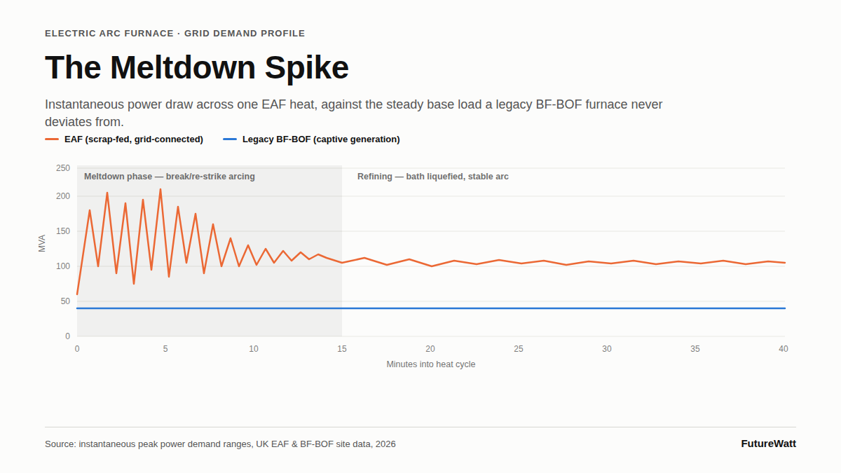
The two technologies present almost inverse load signatures to the network. BF-BOF draws a stable, largely self-generated base load; EAF draws a volatile, grid-dependent load with power quality characteristics that a synchronous captive generator never has to negotiate.
Steelmaking Technology | Primary Energy Vector | Instantaneous Peak Power Demand (MVA) | Specific Electrical Consumption (per liquid tonne) | Grid Stability & Power Quality Phenomenon |
|---|---|---|---|---|
Legacy Integrated BF-BOF (Coal/Coke Core) | Metallurgical coke — embedded off-gas generation with captive steam turbines | 30–50 MVA continuous base-load | 450–600 kWh (highly thermal-reliant, coke-dominant) | Minimal disturbance — stable internal synchronous generation buffers the site from the transmission network |
High-Power AC Electric Arc Furnace (Modern Scrap-EAF) | Direct high-voltage grid connection, typically 275 kV or 400 kV | 150–250 MVA in highly volatile, intermittent spikes | 350–450 kWh (purely electrical) | Extreme phase unbalance, voltage flicker and severe harmonic distortion during the initial scrap meltdown phase |
The Physics of the Meltdown: Voltage Flicker and Harmonic Distortion
The EAF's power quality problem is concentrated almost entirely in the meltdown phase of each heat, before the bath liquefies into a stable, low-resistance pool.
- The Initial Meltdown Volatility: During the first 10 to 15 minutes of an EAF heat, the physical collapse and shifting of solid scrap under the electrodes causes the arc to break and re-strike as a repeated short-circuit event. Each break-and-restrike cycle produces massive, sub-second swings in reactive power (ΔQ), which manifest on the local transmission network as severe voltage flicker — a phenomenon measurable in Pst flicker units and directly perceptible as luminance variation in nearby lighting loads.
- The Harmonic Pollution Penalty: The arc itself is a highly non-linear, chaotic impedance and therefore acts as a broadband noise generator, injecting severe triplen and odd-order harmonics — predominantly 3rd, 5th and 7th — back into the National Grid. Left unmitigated, this harmonic content distorts the voltage waveform, overheats adjacent grid and distribution transformers through increased eddy-current and stray losses, and raises the risk of nuisance tripping in protective relay schemes at neighbouring industrial connections.
- The Mitigation Asset Footprint: Controlling this requires multi-million-pound Static Var Compensators (SVCs) or STATCOMs, paired with dedicated static harmonic filter banks tuned to the dominant harmonic orders. These sub-cycle reactive-response assets sit between the EAF transformer and the transmission connection point, dynamically injecting or absorbing reactive power within milliseconds to smooth the voltage envelope in real time and hold flicker and total harmonic distortion within statutory limits.
Grid Constraints & The Peak Load Cross-Over Calculation
Beyond the physics of a single furnace, the UK's transmission network faces a capacity and scheduling problem at fleet scale.
- The Spatial Grid Mismatch: The UK's heavy industrial clusters sit disproportionately at the geographical periphery of the transmission network — South Wales, Teesside, South Yorkshire — regions built out for the load profile of legacy integrated steelworks, not for concentrated 200 MVA-class EAF connections. Absorbing an EAF fleet at these nodes requires multi-year, multi-hundred-million-pound capital deployment by National Grid Electricity Transmission (NGET) to reinforce substations, uprate transformers and, in several cases, rebuild overhead line routes.
- The Wind Arbitrage Sync: In principle, EAF melting schedules can be synchronised with peak offshore wind generation windows through dynamic industrial demand-side response (DSR), concentrating high-intensity heats into periods of low system-wide marginal carbon intensity and low wholesale pricing. In practice this requires furnace scheduling systems, scrap logistics and workforce rostering to flex around a variable resource, which is operationally harder than it is financially attractive.
- The Volumetric Fleet Equation: The binding constraint is the crossover point at which several high-capacity EAF units, melting in overlapping or coincident schedules, sum to a regional demand that matches or exceeds the transmission boundary's firm capability. Beyond that crossover, the network requires automated intertripping schemes to shed EAF load within cycles of a boundary violation, and increasingly, localised battery energy storage systems (BESS) sized specifically to buffer the instantaneous load steps of the meltdown phase rather than to provide bulk energy arbitrage.