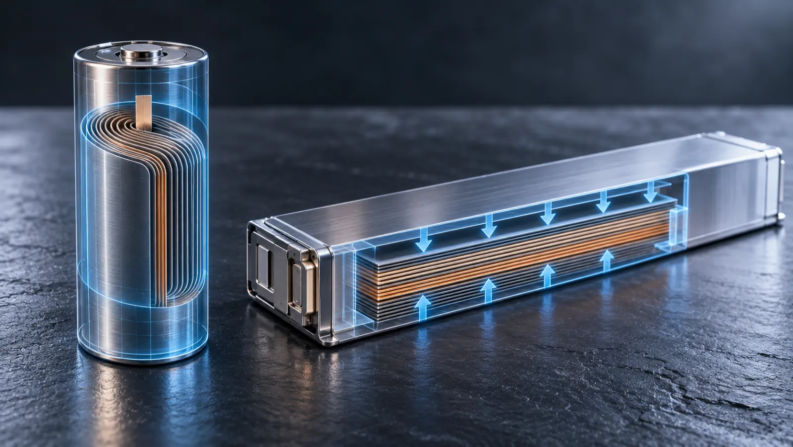
The argument between Tesla’s 4680 and BYD’s Blade is usually framed as a contest between two brands. It is better understood as a contest between two geometries, each of which solves the same set of constraints by sacrificing a different term. A cylinder is the most mechanically self-supporting shape a wound electrode can take, and it carries a hard geometric penalty in the form of void space. A long, thin prism removes that penalty and inherits a different one: a very long current path and a very large cell whose failure costs far more than a single cylinder. This article audits both architectures from first principles, using the packing mathematics, the foil-resistance model, the heat-conduction equations and the structural mechanics that actually decide their performance. Where a figure is an illustrative modelling assumption rather than a published specification, it is stated as such.
1. Geometric packing efficiency and the void-space penalty
Start with the hard mathematical ceiling on cylinders. The densest possible packing of equal circles on a plane is hexagonal, with a packing fraction of π / (2√3) = 0.9069. Each cylinder of radius r occupies a hexagonal unit cell of area 2√3 · r2 (about 3.464 r2) while the circle itself covers π r2 (about 3.142 r2). The remainder, roughly 0.322 r2 or 9.31% of the plan area, is interstitial void that no amount of clever winding can recover. A square array is considerably worse at π / 4 = 0.7854, leaving 21.46% void, which is why serious cylindrical packs are laid out hexagonally wherever the busbar and thermal layout allows it.
That 90.69% figure is a theoretical maximum for touching, infinitely extended circles. A real pack never reaches it, for three reasons. First, cells cannot touch: they need a gap for the structural adhesive or potting compound, for tolerance stack-up and for the thermal interface. Second, the array is finite, so edge cells waste a perimeter of void against the pack wall. Third, thermal management hardware occupies volume that cells cannot. Consider a 4680 cell, 46 mm in diameter and 80 mm long, which occupies about 0.133 litres. At a hexagonal centre pitch p, the plan area per cell is (√3 / 2) · p2, so the in-plane packing fraction is π r2 divided by that area. With a 1 mm inter-cell gap (p = 47 mm) the fraction falls to about 86.9%. With a 2 mm gap (p = 48 mm) it falls to about 83.3%. Insert a cooling ribbon that snakes between rows and the effective in-plane fraction drops again, typically into the high seventies, before a single millimetre of end-plate, busbar layer or pack lid has been counted.
The prismatic case follows the opposite logic. A rectangular cell tessellates with itself exactly: the packing fraction of a rectangle array is 100% of the envelope, and the only losses are the cell can wall, the inter-cell gap and the end structures. A Blade cell of roughly 960 mm × 90 mm × 13.5 mm has a volume of about 1.17 litres, nearly nine 4680 cells in a single can, and its flat faces stack without any geometric void. This is the mechanism behind BYD’s claim that Blade cell-to-pack integration lifts pack volume utilisation by around half compared with a conventional LFP module pack, to somewhere above 60% and, in the better implementations, towards 70%. Those figures are BYD’s and are best treated as a vendor claim, but the direction of the geometry is not in doubt.
It is important to be precise about what “volumetric efficiency” means, because the two sides use the figure differently. Pack-level volumetric efficiency is the ratio of the active cell volume to the whole pack envelope, including lid, floor, cooling plate, busbars, electronics and crash structure. A cylindrical pack beginning from a 90.69% geometric ceiling and losing to gaps, cooling and structure ends up with an envelope utilisation that is often quoted in the 45% to 55% range. A prismatic pack beginning from 100% loses less to geometry but still pays for the rigid end structures that make the cells act as beams. The gap between the two is therefore smaller than the raw 9.31% void figure suggests, and larger than it would be if cylinders were free to touch. Crucially, volume efficiency is not energy efficiency. A tighter pack of lower-energy-density LFP can still deliver fewer kilowatt-hours per litre of pack than a looser pack of high-nickel cylinders, which is exactly the trade the matrix further down quantifies.
2. Internal resistance and tabless current collection
The electrical argument for the 4680’s tabless architecture is a piece of elementary circuit theory that is easy to state and easy to overlook. A wound electrode is a long, thin strip of foil. In a conventional cell a tab welded at one point carries the entire current out of that strip, so every electron generated at the far end of the strip must travel the full unrolled length of the foil to reach it. That path is the dominant source of ohmic loss inside the foil.
Model the foil as a strip of length ℓ, width w and thickness t, with resistivity ρ. Its sheet resistance is Rs = ρ / t. If current is collected uniformly along the strip and exits at a single tab at one end, the current at distance x from the tab is I(1 − x / ℓ), because the foil closer to the tab carries the current from everything behind it. The Joule power dissipated in the foil is then the integral of that current squared times the resistance per unit length, which gives
Psingle tab = I2 Rs ℓ / (3w)
In other words one third of the strip’s end-to-end resistance, multiplied by I2. Adding tabs divides the length each tab must serve. For n equally spaced tabs the loss falls as 1 / n2, so a tab in the middle of the strip (two half-length paths in parallel) cuts the foil loss to one quarter of the end-tab value, and four tabs cut it to one sixteenth.
The tabless design removes the longitudinal path altogether. The electrode foil is left uncoated along one edge, and that edge is folded, shingled or notched and flattened to form a continuous collector face that is welded to a current collector plate across the end of the cell. Now each element of foil sends its current across the foil width, a distance of at most w, rather than along its length. Repeating the integral across the width gives
Ptabless = I2 Rs w / (3ℓ)
The ratio of tabless to single-tab foil loss is therefore (w / ℓ)2. Take illustrative values for a 4680-class electrode: a foil width of 75 mm and an unrolled electrode length of 3.5 m (both assumptions for the purposes of the model, not Tesla-published figures). The ratio is (0.075 / 3.5)2, about 4.6 × 10⁻⁴, a reduction of more than three orders of magnitude in the foil term. Using an 8 micrometre copper anode foil (Rs of about 2.1 mΩ per square), a single end tab gives an end-to-end foil resistance near 98 mΩ, which at a 75 A (roughly 3C) discharge would dissipate on the order of 180 W in the anode foil alone. A centre tab brings that to about 46 W, four tabs to about 11 W, and the tabless geometry to well under one watt. Those numbers show why a cell of this diameter could not realistically be built with a single tab: the heat would be generated in the one place it is hardest to remove.
Two caveats keep the result honest. The model covers the foil only; the total cell resistance also includes the electrolyte ionic resistance, the charge-transfer resistance at both electrodes, the separator, and the contact resistance at the welded collector plate. Once the foil term has been driven close to zero, those terms dominate, so the improvement in total cell DC resistance is much smaller than the improvement in the foil term alone. The second caveat concerns uniformity. A single tab at the cell edge produces a potential gradient across the electrode, so the end nearest the tab carries a higher current density, ages faster and plates lithium first under fast charging. The tabless collector flattens that gradient, which is as valuable to cycle life and fast-charge capability as the raw reduction in Joule heating.
Now apply the same model to the Blade. A long-foil prismatic cell is the architecture the tabless argument warns against, but it is not the same as a single wound strip. A Blade-type cell stacks many electrode layers in parallel, each layer being a rectangle of roughly cell length by cell height, with current collected at the ends of the 960 mm length. The foil resistance of each layer is large, because the path is long and the layer is thin, but N layers in parallel divide the effective foil resistance by N. With an assumed 60 layers per electrode polarity, an end-collected layer of 0.95 m by 0.085 m gives an effective foil resistance of roughly 0.4 mΩ per electrode, or about 0.13 mΩ after the one-third integration factor. That is a modest term compared with the electrochemical resistance of a cell of this size. So the long-foil prismatic penalty is not primarily a heating problem at conventional rates. It is a current-distribution problem: across a 960 mm length the potential drop along the foil makes the ends nearest the tab work harder than the middle, and the effect grows with charge rate. That is consistent with BYD’s reported move to a revised cell geometry for very high-rate flash charging, a shorter current path being the obvious engineering response, although the new dimensions have not been independently published.
3. Thermodynamics: heat dissipation and thermal runaway kinetics
Heat generated inside a cell must conduct to a cooled surface, and the geometry of the cell sets how far it has to go. For uniform volumetric heat generation q′′′ in a solid with conductivity k, the temperature rise from the centre to a cooled surface is q′′′ R2 / (4k) for a cylinder of radius R, and q′′′ L2 / (2k) for a slab of half-thickness L cooled on both faces. Those two expressions make the comparison straightforward.
For the 4680, R = 23 mm, so R2 / 4 = 1.32 × 10⁻⁴ m2. For the Blade, the half-thickness is 6.75 mm, so L2 / 2 = 2.28 × 10⁻⁵ m2. At equal volumetric heat generation and equal through-layer conductivity, the cylinder’s core-to-surface temperature rise is about 5.8 times larger than the thin prism’s. Put numerically with an assumed radial conductivity of 1 W/(m K) and a heat generation of about 42 kW/m3 (roughly 5.6 W in a 4680-sized cell at 3C), the cylinder’s centre sits about 5.6 K above its surface; the same heating in a Blade-thickness slab produces a rise below 1 K across its thickness. The cylinder is thermally “thicker” in the one direction that matters most.
The surface-area-to-volume ratio makes the same point. A 46 mm × 80 mm cylinder has a surface area of about 14,900 mm2 for 133,000 mm3, a ratio near 112 m−1. A 960 × 90 × 13.5 mm Blade has about 201,000 mm2 for 1,166,000 mm3, a ratio near 172 m−1, around 1.5 times higher. Heat leaves a cell through its surface and is generated throughout its volume, so a higher ratio means a lower steady-state temperature for the same heating.
The picture changes once heat extraction is considered along the directions the cell actually conducts well. A wound or stacked electrode is highly anisotropic. Across the layers, heat must cross electrode coatings, separator and electrolyte, so the through-layer conductivity is poor, typically around 0.5 to 1.5 W/(m K). Along the layers, heat runs through continuous aluminium and copper foil, so the in-plane conductivity is one to two orders of magnitude higher, tens of W/(m K). In a conventional wound cylinder the foil runs around the axis and the radial direction is the poor one, so heat has to cross the whole roll to reach the can wall. The tabless design changes this: because the foil edges now form a continuous metallic face at each end of the cell, the axial direction is also a high-conductivity path, and a cooling plate bonded to a cell end can extract heat along the foil rather than across it. Run the numbers for an 80 mm axial path at an in-plane conductivity of 30 W/(m K): the temperature drop is q′′′ H2 / (2k) for a single cooled end, about 4.5 K at the same heating. The Blade has an equivalent route. Cells in a Blade pack stand on their long edge with the cooling plate contacting the 960 mm × 13.5 mm face, so the 90 mm cell height is conducted along the foil planes; at the same assumed conductivity and heating the rise is about 5.7 K. The two architectures end up in a similar place thermally under normal operation, which is why the honest conclusion is not that one runs cooler but that each depends on a particular cooled face being well bonded and that each pays for failure of that interface differently.
Runaway behaviour is where chemistry takes over from geometry. A layered nickel-rich cathode, whether NMC or NCA, is metastable when charged. Above roughly 200 to 250 degrees Celsius (lower for higher nickel content and higher state of charge) the delithiated layered oxide undergoes phase transitions from layered to spinel to rock-salt structures and releases molecular oxygen. That oxygen reacts exothermically with the organic carbonate electrolyte, driving the cell temperature up in a self-accelerating loop, and the process can propagate to neighbouring cells. The preceding steps, SEI decomposition from about 80 to 120 degrees and separator collapse from about 130 degrees, are the early warnings; the oxygen release is the point at which the reaction becomes impossible to stop by cooling.
Lithium iron phosphate has a different structure. Its oxygen is held in phosphate (PO4) tetrahedra by strong covalent P–O bonds, and the delithiated FePO4 framework remains stable to far higher temperatures, with oxygen release not occurring until well beyond the temperatures a cell reaches in a typical abuse event. The result is a runaway onset that sits at a much higher temperature than for nickel-rich chemistries and a substantially lower total heat release. LFP can still vent and burn, since the electrolyte and the graphite anode remain flammable, but the chain reaction does not have the same self-supplied oxidant. This is the single largest safety advantage the Blade has over the 4680, and it is a property of the chemistry, not the shape.
Cell size matters for propagation as well, and it matters in opposite directions. A 4680 holds on the order of 90 to 100 Wh, so the energy released by one failing cell is small and a pack designer can separate cells with intumescent or foam material so that one event does not heat its neighbours past their own onset temperature. A Blade cell holds several hundred watt-hours, so a single failure is a larger event, but its LFP chemistry releases far less heat per unit of stored energy. The relevant figure is the product of stored energy and fractional heat release, and for the LFP Blade that product remains lower than for a nickel-rich cylinder even though the individual cell is far bigger.
4. Structural integration and the load path
Both architectures are attempts to turn cells from passive cargo into structure. The principle is the sandwich panel. A sandwich beam of two stiff skins separated by a lightweight core has a bending stiffness per unit width of approximately Ef tf d2 / 2, where Ef and tf are the skin modulus and thickness and d is the distance between skin centroids. The core’s job is to hold the skins apart and to carry the shear between them. Doubling the pack depth quadruples the stiffness of the sandwich, which is why a thick battery pack under the floor is an efficient place to put structural material, provided the cells can carry shear load without crushing.
Torsion is governed by the closed-section behaviour of the whole body. For a thin-walled closed section the torsional constant is J = 4Am2 t / p, where Am is the enclosed mid-line area, t the wall thickness and p the perimeter. A battery pack contributes to J because it closes the underbody into a wide, shallow box, and the more rigidly its walls and floor are tied to the surrounding sills, the more it adds. The pack’s contribution depends on how well it is bonded to the body, not simply on how stiff its own contents are.
Tesla’s route to this is the potted cylindrical array. Cells stand vertically between a top and a bottom skin, the gaps between them are filled with a structural polyurethane adhesive or foam (described in Tesla’s patent filings and by teardown observers, and in some descriptions with intumescent properties for fire protection), and the whole assembly becomes a stressed floor. Each cylinder acts as a column resisting compression between the skins, while the potting compound transfers shear between neighbouring cells and between the cells and the skins. The pack’s outer frame then ties the front and rear megacastings together, so longitudinal loads in a frontal or rear impact can pass through the floor rather than around it. The weakness of the arrangement is the interface: the adhesive has to remain bonded across temperature cycles, vibration and decades of ageing, and the cells themselves, being thin-walled cans, are good in axial compression and relatively poor in side loading.
BYD’s route is the beam array. Blade cells are long enough to span the pack width, and are laid side by side so that the cells themselves, together with an aluminium sandwich panel with a honeycomb-like internal structure, form the load-bearing floor. Because each cell is a long, thin, rectangular beam, it contributes directly to the pack’s bending and shear stiffness, in the manner of the cross-members of a conventional ladder floor. BYD has quoted a torsional stiffness of the order of 40,000 N m per degree for its cell-to-body vehicles, a vendor claim that should be treated as such, but one that is consistent with a pack that has been designed as a body member from the outset. The corresponding weakness is that the cell cans are load-bearing, so any damage to a can wall during an impact is both a structural and a safety event, and the large cell size means a single localised failure involves more energy.
5. Gigafactory manufacturing economics
The manufacturing comparison is where the two philosophies diverge most. Tesla’s 4680 programme has been built around cutting factory capital intensity per gigawatt-hour through a combination of larger cylinders, which cut the number of cells handled per pack, and dry-battery-electrode (DBE) processing, which removes the solvent-based coating and drying line.
In a conventional wet process the active material, conductive carbon and binder are mixed into a slurry with the solvent N-methyl-2-pyrrolidone (NMP) for the cathode, or water for the anode, coated onto the foil, and then dried in a long, energy-hungry oven that also has to recover the solvent. The coating and drying line is among the largest, most energy-intensive and most expensive parts of an electrode plant. DBE replaces it by mixing the powders with a polytetrafluoroethylene (PTFE) binder, which is fibrillated by shear into a web that holds the active material together; the resulting free-standing film is then laminated onto the foil by calendering. The promised benefits are a smaller plant footprint, no solvent recovery and lower drying energy.
The difficulties are mechanical and electrochemical. Calendering a free-standing dry film onto foil requires high roll pressure and often elevated temperature, and the film must be uniform in thickness and density across the full web width; small variations in porosity translate directly into local differences in current density and lithium plating risk. Spring-back after calendering can disturb the final electrode density. The PTFE binder is also electrochemically fragile at the low potentials of a graphite anode, where lithiated graphite can reductively attack the fluorinated polymer, so anode formulation has been the harder problem and the cathode, which operates at higher potential, was generally the easier fit. Tesla has described dry anode processing as running on its 4680 lines and has reported progress on a dry cathode; the pace of the cathode transition, and the yield it achieves at scale, are the figures to watch rather than any single announcement.
BYD’s approach is the conventional wet slurry process taken to very high speed and very high yield. Its advantage is process maturity. Wet coating is a well understood science, the LFP chemistry it uses is tolerant of coating variation, and the stacked-electrode lamination used to build long prismatic cells can be run continuously. Its constraints are of a different kind. Stacking hundreds of electrode layers over a 960 mm length demands tight control of electrode and separator alignment, edge burrs and particulate contamination, because a single internal short in a large cell scraps far more stored energy than one in a small cylinder. That is a yield-compounding problem: a cylinder rejected at end-of-line loses about 90 Wh of product, a Blade cell rejected for the same reason loses several hundred. BYD’s vertical integration, from cathode material through cell to pack to vehicle, softens the economics by letting it absorb and optimise the full chain.
Pack assembly follows the same logic. A 4680 structural pack contains hundreds to over a thousand cells, which must each be handled, bonded and connected, so the number of operations per pack is high but each is simple and parallelisable. A Blade pack contains on the order of a couple of hundred cells, so the operations per pack are far fewer but each cell is large, heavy and unforgiving, and the pack’s structure is bonded together in a way that makes repair difficult, as teardown work on the latest Blade generation has noted.
6. Comparative matrix
| Battery Architecture Metric | Tesla 4680 (Tabless Cylindrical) | BYD Blade (Structural Prismatic) |
|---|---|---|
| Cell geometry | 46 mm diameter × 80 mm height, about 0.133 L and roughly 90–100 Wh per cell | About 960 × 90 × 13.5 mm, around 1.17 L and several hundred Wh per cell |
| Cathode chemistry | High-nickel layered oxide (NMC or NCA family) | Lithium iron phosphate (LFP) |
| Geometric packing ceiling | 90.69% hexagonal limit; about 83–87% once a 1–2 mm gap is added; lower again with cooling ribbon | Close to 100% tessellation of the envelope; losses are can wall, gap and end structure |
| Surface-area-to-volume ratio | About 112 m−1 | About 172 m−1 (around 1.5 times higher) |
| Dominant Physical/Chemical Mechanism | Tabless continuous-edge current collection shortens the electron path from the electrode length to the foil width, cutting foil Joule loss by a factor of (w / ℓ)2; oxygen release from the delithiated layered cathode governs runaway | Rectangular tessellation removes void space; strong P–O covalent bonds in the phosphate lattice keep oxygen locked in, delaying and weakening runaway |
| Pack-Level Engineering Advantage | Higher cell-level gravimetric energy density, low internal resistance and high power; potted cells form a stressed floor that links front and rear megacastings | Pack volume utilisation of about 60% to 70% (vendor claim); cells act as cross-beams in a honeycomb-like aluminium sandwich, giving high torsional stiffness and fewer parts |
| Primary Manufacturing/Thermal Constraint | Dry-electrode calendering uniformity and PTFE stability at the anode; heat conducts poorly across the roll radius (about 5.8 times the Blade’s core rise at equal heating); adhesive potting must survive thermal cycling | Alignment, burr and contamination control over 960 mm of stacked layers; current distribution along a long foil at high rates; large per-cell energy raises the cost of a single reject and complicates repair |
| Cell-level energy density | Higher, with teardown estimates in the region of 240–270 Wh/kg | Lower, around 160 Wh/kg for the original cell (independent teardown) |
7. What the physics says for engineers, fleets and investors
For a battery engineer, the two architectures are not rivals on a single scale but answers to different optimisation problems. The 4680 maximises energy and power per kilogram and reduces the factory capital cost per cell, and it accepts a geometric void penalty, a relatively thick thermal path across the cell radius and a dependence on nickel-rich chemistry with its attendant runaway behaviour. The Blade accepts a lower energy density per kilogram in return for geometric efficiency, intrinsic chemical safety and a structure that doubles as a body member, and it pays for that with a long current path, a heavy yield penalty per failed cell and a pack that is hard to repair.
For a fleet director, the decision turns on duty cycle. A vehicle that is weight-sensitive, high-power or range-critical benefits from the higher gravimetric density of a nickel-rich cylinder. A vehicle that cycles heavily, charges to 100% routinely, or operates where thermal safety and cycle life dominate the total cost of ownership benefits from LFP’s tolerance of deep cycling and its higher runaway threshold. The heavy repair penalty of a bonded cell-to-body pack needs to be priced into insurance and end-of-life assumptions for either architecture.
For an institutional investor, the relevant questions are manufacturing questions. Tesla’s thesis depends on dry-electrode yield and throughput at scale; until the cathode process is demonstrated at yield, the capital-cost advantage remains a projection. BYD’s thesis depends on sustaining its vertical integration and on whether its larger cell format can be made to charge at very high rates without a current-distribution penalty. Neither has yet shown that its architecture dominates across all of these axes, and the physics suggests that neither will, because the trade-offs are structural rather than a matter of execution.
The shape of a cell is a design decision with consequences that run from the electron path in a foil to the stiffness of a car body. The cylinder and the prism each choose which of those consequences to accept. Understanding the maths behind that choice, from the 90.69% packing ceiling to the (w / ℓ)2 reduction in foil loss to the square-law sensitivity of sandwich stiffness to pack depth, is what separates a defensible procurement or investment case from one based on branding.