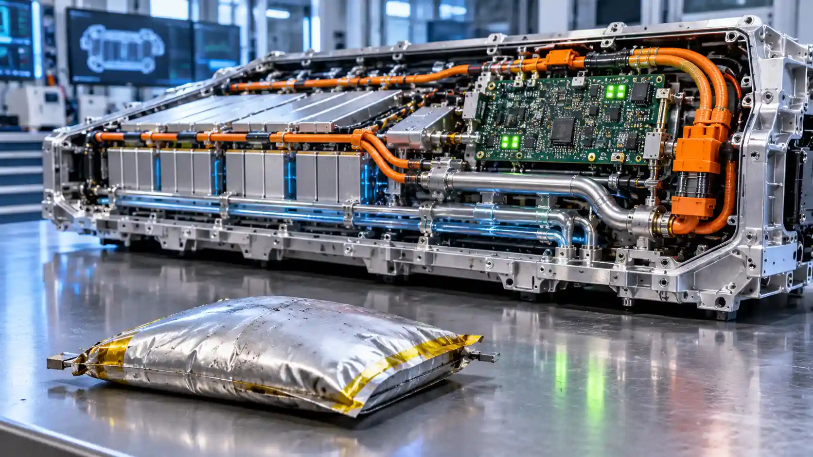
Few comparisons are repeated as often, or with as little engineering scrutiny, as the claim that an electric vehicle (EV) battery will degrade like a smartphone battery. The intuition is easy to understand. Both devices store energy in lithium-ion cells, both are charged from a socket, and nearly everyone has experienced a phone that held a day of charge when new and barely lasted an afternoon after three years. The inference that a car will follow the same trajectory, only at greater expense, is then drawn almost automatically. It is also wrong, and wrong in a way that matters commercially. It inflates perceived residual value risk, distorts used vehicle pricing, and misdirects attention from the variables that actually govern traction battery life. This article calls the error the form-factor fallacy: the assumption that shared chemistry implies shared behaviour, when in practice the cell format, thermal environment, voltage window and control architecture differ so completely that the two products belong to different engineering categories.
The analysis is written for automotive systems specifiers, energy storage software architects and clean-tech investment analysts. It proceeds in five parts. It first contrasts the materials and mechanical structure of consumer and automotive cells. It then audits the thermal environment, comparing active liquid cooling with passive ambient dissipation. It quantifies the software state-of-charge (SoC) buffers that keep automotive cells away from their most damaging operating points, and profiles the Battery Management System (BMS) topologies that balance cells and track impedance, in contrast to the fuel-gauge integrated circuits found in mobile electronics. It closes by consolidating the evidence into a comparative matrix and drawing implications for specification, software architecture and valuation. Throughout, numerical values are representative engineering ranges and not figures for a specific product, since individual designs vary by manufacturer.
Shared chemistry, different engineering categories
A lithium-ion cell stores energy by shuttling lithium ions between a graphite-based anode and a metal oxide or phosphate cathode through a liquid electrolyte. That description applies equally to the cell in a phone, a laptop, a power tool and a car. Everything else about the product is a design decision, and those decisions are driven by what each market values. A smartphone is a thin, sealed, cost-sensitive consumer product with a replacement cycle of two to four years, in which every cubic millimetre of volume is contested by the display, camera modules, antennas and logic board. The battery is therefore optimised for volumetric energy density, because a thicker battery means a thicker or shorter-lived device in the eyes of the buyer. Longevity beyond the expected ownership period is a secondary consideration, and the supporting systems are minimised to preserve volume and cost.
An EV traction pack is designed against a completely different brief. It must deliver a service life measured in a decade or more and in hundreds of thousands of kilometres, it is warranted by the manufacturer against capacity loss, and its failure modes include safety consequences at a scale that no handset presents. Its cost is a large share of the vehicle, so the economics favour spending on cooling, monitoring, structure and software if that spend extends life. Volumetric density still matters, but it is traded against longevity, safety and thermal stability rather than maximised at their expense. The pack is therefore a system of cells, cooling, structure, power electronics and software and not just a larger battery. The remainder of this article examines how each layer of that system suppresses the ageing mechanisms that shorten the life of a consumer cell.
Electrochemical and structural divergence
Cathode chemistry: high-cobalt oxides against stabilised lattices
The cathode determines the voltage window, the energy density and much of the structural behaviour of a cell. Smartphone cells have historically used lithium cobalt oxide (LCO) or cobalt-rich derivatives, because LCO offers very high volumetric energy density in a compact layered structure. To squeeze more capacity out of a fixed volume, manufacturers have progressively raised the upper charge voltage of these cells, with modern high-voltage handset cells charging to around 4.4 volts or higher per cell. At those potentials a large fraction of the lithium is extracted from the layered lattice, and the structure becomes progressively unstable. The cathode surface reacts with the electrolyte, oxygen can be lost from the lattice near the surface, cobalt dissolves, and the crystal undergoes phase transitions that crack and reconstruct the particle. These effects are the principal reason that a high-cobalt consumer cell loses capacity quickly when charged to its limit.
Automotive cells use chemistries chosen for a different compromise. Layered nickel-manganese-cobalt (NMC) and nickel-cobalt-aluminium (NCA) oxides dilute the cobalt content and, in most designs, are charged to a lower upper voltage, typically around 4.2 volts per cell or a little less, with the pack software enforcing further margin. The presence of manganese or aluminium stabilises the layered lattice and moderates the structural changes that accompany deep delithiation. Lithium iron phosphate (LFP) takes the stabilisation principle further. Its olivine crystal structure is held together by strong phosphorus-oxygen covalent bonds within the phosphate groups. The framework changes very little in volume as lithium enters and leaves, it does not release oxygen readily even under abuse, and it operates at a lower and very flat voltage near 3.2 to 3.3 volts. The trade-off is lower energy density, which is acceptable in a vehicle with the space for a larger pack but would be commercially unacceptable in a handset. The consequence is that the dominant cathode ageing mechanisms of consumer cells are either absent or heavily suppressed in automotive cells.
Cell format and mechanical constraint
The physical format of the cell is the second major point of divergence. A typical smartphone battery is a thin pouch cell: electrode layers are stacked or wound and sealed in a flexible laminated aluminium envelope. The pouch is light and efficient in its use of volume, but it provides almost no mechanical constraint. During charging, the graphite anode expands by roughly ten per cent in volume on full lithiation, and gas generated by electrolyte decomposition accumulates inside the sealed pouch. Without external pressure, the electrodes can lose uniform contact, layers can delaminate, and the cell can visibly swell. Swelling is not only a cosmetic symptom. It indicates gas evolution and loss of electrode contact, both of which accelerate capacity loss and raise internal resistance, and in severe cases it creates a safety hazard.
Automotive cells use formats that are either rigid or externally constrained. Prismatic cells have a rigid metal can that holds the electrode stack under pressure and contains gas. Cylindrical cells, of which the 21700 format is a widely used example, have a steel can with a wound jellyroll that is mechanically supported by its own geometry and by the can wall, and most have a pressure-activated vent. Where automotive designers do use pouch cells, the pouches are not left free: they are assembled into modules with compression plates, foam pads or structural frames that apply and maintain a controlled stack pressure. Controlled pressure keeps the electrode layers in contact, restrains swelling, reduces delamination and improves the uniformity of current distribution. The structural pack, in which cells are bonded into a stiff housing that is itself part of the vehicle body, extends the same principle to the whole assembly. The result is that mechanical degradation pathways, including particle cracking from unrestrained expansion and contact loss between layers, are managed by structure and not left to chance.
Electrode loading and particle engineering
Automotive cells are also designed with more conservative electrode architectures. Consumer cells are built with very thick, densely calendered electrodes to maximise energy in a fixed volume. Such electrodes have long ionic diffusion paths, and when charged quickly they develop steep concentration gradients that favour lithium plating on the anode surface. Automotive cells balance energy against power and life, using electrode thicknesses, porosity and particle sizes selected to support the intended charging rates and to distribute strain. Many modern NMC cathodes use single-crystal or otherwise engineered particle morphologies that resist the intergranular cracking that damages the polycrystalline secondary particles common in earlier designs. Cracked particles expose fresh surface to electrolyte, which promotes further growth of the solid electrolyte interphase (SEI) and consumes lithium. Engineering the particle to resist cracking is therefore a direct longevity measure, and it is an area in which automotive cells have received far more development investment than the consumer market has required.
Thermal dynamics: active liquid cooling against passive dissipation
Why temperature governs parasitic reactions
The main chemical process that limits the life of a lithium-ion cell is the continued formation and thickening of the SEI on the anode. The SEI forms from electrolyte reduction products, and while a thin, stable layer protects the anode, a layer that keeps growing consumes cyclable lithium and electrolyte and adds impedance. The rate of this and other parasitic reactions follows an Arrhenius-type temperature dependence, in which reaction rate rises exponentially with absolute temperature. A common rule of thumb is that many ageing processes accelerate by a factor of around two for every ten degrees Celsius of temperature increase. The rule is approximate, but it conveys the key point: modest differences in sustained operating temperature compound into large differences in lifetime. Cold operation is not benign either, since low temperatures slow ionic transport and raise the risk of lithium plating during charging, and so the ideal operating window is a band and not simply a ceiling.
The smartphone thermal environment
A smartphone is a thermally constrained device. It has no fan and no liquid loop, and heat produced by the processor, the display, the radios and the charging circuit must escape through a thin chassis whose outer surface is held by a human hand. Heat accumulates inside, and the battery sits in the middle of the heat sources. During fast wired charging, resistive and conversion losses add several watts of heat inside the case, and if the user is also running a demanding application or the phone is in a warm environment, the internal temperature can rise comfortably beyond 40°C, with the battery regularly soaking in 45°C or more. Charging in a pocket, on a car dashboard or under a pillow reduces dissipation further. The device may throttle charging or processing in response to temperature sensors, but the throttling is crude and is designed to protect the user and the electronics, not to preserve long-term cell health. A cell held at high temperature and high voltage simultaneously, which is common during the final phase of a phone charge, is subject to the worst combination of stresses.
The automotive thermal management system
An EV pack treats heat as a controlled variable. Most modern vehicles use a liquid coolant circuit that passes through cooling plates in thermal contact with the cells, typically beneath the modules or between them, with a thermal interface material filling the gaps. A pump circulates a water-glycol mixture through the plates and then to a radiator, a chiller linked to the vehicle's refrigerant circuit, or a heater, as the BMS and thermal controller require. The system can both remove heat during driving and fast charging and add heat in cold conditions, using a resistive or heat-pump source to bring the pack into its preferred range before charging begins. Many vehicles precondition the pack automatically when a fast charger is selected as the destination in the navigation system, so that the cells arrive at the connector near their optimal temperature.
The target is a narrow operating band. For most chemistries, a cell temperature between roughly 20°C and 35°C represents the sweet spot: warm enough for efficient ion transport and low internal resistance, cool enough to keep parasitic SEI growth, electrolyte decomposition and transition metal dissolution at low rates. The cooling plate and thermal controller hold the pack in that band across a very wide range of ambient conditions and load profiles. The difference in heat management capacity can be illustrated by a simple energy balance. A pack with a 150 kW fast-charge peak and a round-trip efficiency of 95 to 97 per cent in the charging path may dissipate several kilowatts of heat within the cells and the busbars, and a liquid system with a coolant flow rate of several litres per minute can remove that heat while keeping cell-to-cell temperature differences within a few degrees. A passive phone has nothing comparable. Its thermal path is dominated by conduction through the chassis and convection from its outer surface to the air, which together can remove only a few watts.
Temperature uniformity matters as much as the average. If one region of the pack runs hotter than another, the hot cells age faster, their capacity diverges from the others, and the weakest cell begins to limit the entire series string. Cooling plate design, coolant routing and thermal interface selection are therefore as much about balancing temperature across the pack as about reducing it. The BMS monitors temperature through multiple sensors distributed across the modules and applies derating, reducing the charge or discharge current, if any cell approaches a limit. The control loop runs continuously and with far finer granularity than the thermal governors in a mobile device.
Software buffers and state-of-charge constraints
The gap between the displayed and the physical range
One of the least appreciated differences between a consumer device and a vehicle is that the state of charge displayed to the user is not the true physical state of charge of the cell. In a vehicle, the BMS defines a usable window that is narrower than the full physical capacity of the cell. A displayed value of 100 per cent corresponds to a cell voltage that is deliberately set below the cell's maximum, and a displayed value of 0 per cent corresponds to a voltage that is deliberately held above its minimum. The hidden margins at the top and bottom of the window are commonly called buffers. They are invisible to the driver, who sees only a full-to-empty indicator, but they are among the most effective longevity measures in the entire system.
The size of the buffers varies by design and chemistry. Depending on the vehicle, the usable window may represent somewhere between roughly 85 and 97 per cent of the cell's nominal capacity, with a few per cent held in reserve at each end. For a pack with a nominal gross capacity of 64 kWh and a usable capacity of 60 kWh, the buffer is 4 kWh, or about 6 per cent, shared between the top and bottom of the window. These figures are illustrative, and manufacturers do not generally publish the exact margins, but the principle is consistent across the industry. Some vehicles also expose a user-selectable daily charge limit, commonly 80 or 90 per cent of the displayed value, which in effect adds a third, adjustable buffer on top of the factory margins.
Why the extremes are the most damaging
The reason for the buffers is the non-linear relationship between voltage, state of charge and degradation rate. At high SoC, the anode potential approaches that of lithium metal and the cathode is highly delithiated, which together increase the rate of electrolyte oxidation at the cathode, SEI growth at the anode, and the risk of lithium plating during charging. In layered oxide cathodes, the structural stresses of deep delithiation are greatest at the top of the voltage range. At low SoC, different mechanisms operate. If a cell is discharged too deeply, the anode potential can rise to the point at which copper current collectors begin to dissolve, and the dissolved copper can redeposit as metallic dendrites on subsequent charge, creating a latent short-circuit risk. Deep discharge also stresses the cathode and can cause irreversible structural changes. Avoiding the absolute extremes, true 0 per cent and true 100 per cent physical saturation, therefore removes the portions of the cell's operating range in which per-cycle damage is highest.
The effect on lifetime can be substantial. Cycle life testing of lithium-ion cells consistently shows that limiting the depth of discharge and the upper voltage extends the number of cycles to a given capacity retention, often by a large multiple. A cell cycled across a narrow, mid-range window may deliver several times as many cycles as the same cell cycled across its full range. In a vehicle, the buffers give the pack a built-in measure of this benefit on every cycle, without any action by the driver, and the optional charge limit extends it for users who choose to apply it. A phone, by contrast, commonly charges to the highest voltage its cell can tolerate and discharges to the lowest, because the manufacturer's priority is to maximise the runtime that the customer sees on the first day. Some handsets now include optimised charging features that hold the battery at around 80 per cent overnight, and these are effectively a small-scale version of the buffer principle, but they are optional and limited by the absence of the other supporting systems.
Capacity accounting as the buffers are consumed
Software buffers also give automotive designers a mechanism to disguise the early capacity loss that every cell undergoes. As the SEI stabilises and the cell loses a small proportion of its cyclable lithium, the BMS can in some designs widen the usable window slightly, using a portion of the reserved margin so that the displayed capacity falls less than the true capacity. This technique is a design choice and not a universal feature, and it should be understood as part of the reason that reported State of Health (SoHealth) figures in automotive datasets tend to decline slowly: some of the underlying cell ageing is absorbed by the margin before it becomes visible in the usable capacity. The practice is legitimate when it is accompanied by transparent warranty terms, but it is a reminder that a vehicle SoHealth number is a managed quantity and not a raw physical measurement.
BMS architecture: cell balancing and impedance tracking
The fuel gauge in a mobile device
The electronics supervising a smartphone battery are intentionally simple. A fuel-gauge integrated circuit, typically a single chip, measures the voltage of the battery as a single unit, measures the current through a small sense resistor, and applies a model to estimate the remaining charge. Alongside it is a protection circuit that disconnects the cell in the event of over-voltage, under-voltage, over-current or short circuit, and a temperature sensor, usually a single thermistor. Because the battery consists of one cell, or a very small number of cells, there is no balancing problem to solve. The gauge learns the capacity of the cell over time and adjusts its estimates, but its model is simple, its corrections are crude, and its typical response to a failing cell is to report an inaccurate charge level, as users know from phones that shut down at 20 per cent. The architecture is adequate for a product that is replaced every few years, and it is economical in cost, space and power.
The automotive master-slave topology
A traction pack consists of hundreds or thousands of cells, connected in series to reach a high voltage, typically 400 volts or 800 volts, and in parallel to reach the required capacity. In a series string, the same current passes through every cell, so the weakest cell, with the lowest capacity or the highest resistance, determines when the entire string must stop charging or discharging. A mismatch of even a few per cent between cells therefore translates directly into lost usable capacity and, if left uncontrolled, to the accelerated degradation of the weakest cells, which are driven harder than the rest. Managing this problem demands a purpose-built architecture.
The common solution is a distributed or master-slave BMS. Slave boards, often called cell monitoring units, are mounted on or near each module and measure the voltage of every cell group, typically to an accuracy of a few millivolts, along with several temperature points. They communicate over an isolated bus, such as a controller area network or a daisy-chained serial link, with a master controller that aggregates the data, runs the estimation algorithms, controls the contactors, requests thermal management actions and communicates with the vehicle. Current is measured by a precision shunt or Hall-effect sensor at the pack level, and the isolation monitoring system watches for leakage between the high-voltage system and the chassis. The master evaluates every cell group against voltage, temperature and current limits many times per second and can derate or disconnect the pack in milliseconds if a limit is violated. This is a safety-rated control system, developed under functional safety standards, and its complexity and cost reflect that role.
Passive and active balancing
The BMS counters cell divergence through balancing. In passive balancing, each cell group has a bleed resistor and a switch; when a group is measured at a higher voltage than its neighbours near the top of charge, the BMS closes the switch and dissipates a small amount of energy as heat, typically with a balancing current in the range of tens to a few hundred milliamps, until the voltages converge. Passive balancing is simple, robust and inexpensive, and it is sufficient for many designs, particularly when cells are well matched at manufacture. Its limitation is that it wastes energy and acts slowly, and it can only reduce the charge of stronger cells to match the weaker ones.
Active balancing moves charge between cells using capacitors, inductors or transformers, taking energy from stronger cells and delivering it to weaker ones. It is more efficient, can operate during discharge as well as charge, and can recover usable capacity that passive methods discard, but it adds cost, complexity and potential failure points. The choice between the two depends on the cell chemistry, the expected spread of cell parameters, and the cost and reliability targets for the product. For LFP, whose voltage curve is very flat between roughly 10 and 90 per cent SoC, balancing is more difficult in practice, because voltage differences between cells carry very little information about charge difference except near the extremes. LFP packs therefore often rely on balancing near the top of charge and on regular full charges, which is one reason some manufacturers recommend charging LFP vehicles to 100 per cent periodically. In either case, the aim is to keep cell divergence small and to prevent localised voltage stress on any cell.
State estimation and impedance tracking
Beyond balancing, the BMS estimates the internal state of the pack. State of charge is typically computed by a combination of coulomb counting, which integrates the current, and voltage-based correction using an open-circuit voltage model, often fused using an extended Kalman filter or a similar observer. These estimators correct for sensor drift and varying conditions, and in the more advanced implementations they use an equivalent circuit model of each cell that includes resistance and diffusion terms, updated in real time. SoHealth is estimated from changes in capacity and internal resistance, and the BMS tracks the growth of impedance across the pack. Rising impedance in a single cell is an early warning of a developing fault, such as localised lithium plating or contact loss, and can trigger power derating, a service alert or a warranty flag long before the user perceives any change in range.
Impedance tracking also feeds the power limit calculations. The pack's maximum charge and discharge power is a function of its temperature, state of charge and internal resistance, and the BMS recomputes these limits continuously so that no cell is driven beyond its safe current at any moment. In this way the software acts as an active protection layer, adapting to the ageing of the pack and extending its life by reducing stress in proportion to the cell's remaining capability. Some fleets and manufacturers also upload the data to the cloud, where large-scale analytics identify cells or batches that are ageing faster than predicted, and update the BMS parameters over the air. The consumer fuel gauge has no equivalent capability, and the difference in monitoring granularity, from a single voltage reading to thousands of individually tracked cell parameters, is among the clearest demonstrations of why the two products should not be equated.
Comparative matrix: smartphone cell against automotive traction pack
The matrix below consolidates the engineering contrasts discussed above. Values are representative ranges across typical designs and are intended to characterise the categories and not any particular product. Expected lifecycle horizons are indicative of design intent and warranty practice, and actual outcomes depend on climate, usage and charging behaviour.
| Engineering Metric | Consumer Smartphone Cell | Automotive EV Traction Pack | Primary Degradation Accelerator | Expected Lifecycle Horizon |
|---|---|---|---|---|
| Cell chemistry and lattice | High-cobalt layered oxide (LCO or derivatives), charged to roughly 4.4 V or higher. | Stabilised layered NMC or NCA at around 4.2 V or below, or olivine LFP at roughly 3.2 to 3.3 V. | Phone: surface reactivity, oxygen loss and phase transitions at high voltage. EV: transition metal dissolution at high heat and SoC (NMC); slow SEI growth (LFP). | Phone: roughly 500 to 800 full cycles to 80 per cent. EV: commonly well over 1,000 and, for LFP, several thousand full cycles. |
| Cell format and mechanical constraint | Thin, unconstrained pouch cell with minimal stack pressure. | Rigid prismatic or cylindrical can, or pouch cells held under controlled compression in a structural pack. | Phone: swelling, gas accumulation, delamination and particle cracking. EV: cyclic strain over very long service. | Phone: two to four years of typical ownership. EV: designed for a decade or more of service. |
| Thermal management | Passive conduction through the chassis; internal temperature of 45°C or more during fast charging or heavy use. | Active liquid-cooled plates with chiller and heater, holding cells in a 20°C to 35°C band. | Phone: sustained heat soak accelerating SEI thickening. EV: only exposure beyond the cooling system's capacity, such as repeated fast charging in extreme heat. | Phone: heat is a first-order limit on life. EV: thermal ageing is suppressed and largely managed. |
| State-of-charge window | Near the full physical range, with only optional overnight holding features. | Hidden top and bottom software buffers, with commonly a few per cent reserved at each end and an optional user charge limit. | Phone: time spent at high voltage and deep discharge. EV: prolonged storage at 100 per cent in hot climates. | Phone: window drives rapid early fade. EV: window extends the plateau phase. |
| Monitoring and balancing | Single fuel-gauge IC, one thermistor and a basic protection circuit; no balancing required. | Master-slave BMS with millivolt-level cell monitoring, many temperature sensors, passive or active balancing and Kalman-filter state estimation. | Phone: inaccurate gauging and uncorrected stress. EV: cell divergence if balancing is inadequate, particularly in flat-curve LFP packs. | Phone: no protection against gradual ageing. EV: continuous correction and early fault detection across the pack life. |
| Design priority | Maximum volumetric energy density and minimum cost at the point of sale. | Balanced energy, safety, power and longevity, backed by a multi-year warranty. | Phone: density prioritised over life. EV: fast charging and high-temperature storage are the principal stressors. | Phone: a consumable. EV: a long-lived structural asset, with warranties commonly spanning around eight years. |
The pattern in the matrix is that each row represents a layer of protection that the phone lacks and the vehicle includes. No single layer is decisive. The longevity of the traction pack emerges from the compounding effect of stabilised chemistry, mechanical constraint, thermal control, voltage buffers and active monitoring, each of which reduces the rate of a different ageing mechanism. Removing any one of them would shorten life, and removing all of them would produce something resembling a phone.
Where the analogy does hold
It would be inaccurate to claim that EV batteries are immune to ageing or that no lessons transfer from consumer devices. The same electrochemistry applies, and the same qualitative stress factors, heat, high state of charge, high charging rate and deep discharge, accelerate degradation in both. A vehicle that is routinely fast charged to 100 per cent in hot conditions and parked at full charge in direct sun will age faster than one that is not, and those effects are measurable. The point of the engineering contrast is not that the stresses vanish, but that the vehicle's architecture attenuates them, so that ordinary use sits in the benign part of the ageing curve while a phone's ordinary use sits in the harsh part. Operators who understand this can reinforce the system's design through charge limits, thermal preconditioning and sensible fast-charging habits, and those who ignore it can partially negate it.
There are also real differences within the automotive category. Vehicles with passive or air-cooled packs, older designs with minimal buffers and low-cost implementations with basic balancing do not enjoy the full set of protections, and their degradation profiles are consequently worse. The first-generation air-cooled EVs that anchor many of the negative anecdotes were designed with less thermal capacity than modern liquid-cooled systems, and their experience should not be extrapolated to current vehicles. Analysts should therefore specify the cooling architecture, chemistry and BMS capability of the asset in question, instead of treating the category as uniform.
Implications for specifiers, software architects and investors
For systems specifiers, the central lesson is that battery life is a system property and not a cell property. Procurement criteria that focus only on cell chemistry or nominal capacity miss the contribution of thermal design, buffer strategy and BMS quality. A specification for a fleet vehicle or a stationary storage system should state the operating temperature band and cooling method, the usable-to-gross capacity ratio, the balancing method and current, the accuracy of cell voltage and temperature measurement, and the warranty terms for capacity retention and throughput. These parameters are better predictors of life than the headline energy figure.
For energy storage software architects, the BMS is a strategic asset. The control topology determines how effectively hardware margins are converted into lifetime, and over-the-air updates allow the control strategy to be refined as field data accumulates. Opportunities include adaptive charge limits that respond to temperature and duty cycle, predictive thermal preconditioning, improved state-of-health estimation that reduces the required safety margin and fleet-level analytics that identify outlier cells early. Because every percentage point of recovered usable capacity or extended life is delivered without additional hardware, software improvement has a favourable return relative to cell chemistry development, and it can be applied to vehicles already in service.
For clean-tech investment analysts, the form-factor fallacy has a direct valuation consequence. Models that assume traction batteries degrade at consumer-electronics rates will overstate depreciation, understate residual values, overestimate warranty provisions and undervalue second-life applications in stationary storage, where a pack retaining 70 to 80 per cent of its original capacity remains commercially useful. As empirical fleet datasets accumulate and show high retention at high mileage, the risk premium attached to battery uncertainty should narrow. The firms best placed to benefit are those with transparent diagnostic reporting, strong BMS and thermal capability, and the data infrastructure to demonstrate the health of their assets to buyers, lenders and insurers.
Conclusion: a system, not a cell
The comparison between a phone and a car is attractive because it is simple, and it fails because it ignores everything that surrounds the cell. A smartphone battery is a high-density, thinly protected component operating in a hot, enclosed environment, charged to its limits and supervised by a minimal fuel gauge. An EV traction pack is an engineered energy system: its cathode chemistry is stabilised or inherently robust, its cells are mechanically restrained, its temperature is held within a narrow band by active cooling, its voltage window is trimmed by hidden software buffers, and its cells are monitored, balanced and diagnosed individually by a safety-rated control architecture. Each layer attacks a specific ageing mechanism, and together they move the cell from the steep early part of the degradation curve onto a long plateau.
The practical conclusion is that consumer experience is a poor guide to automotive battery life. Specifiers should evaluate the system, architects should invest in the control layer, and analysts should price traction batteries as long-lived structural assets whose principal risks are specific, measurable and manageable, instead of as overgrown consumables on a short fuse.