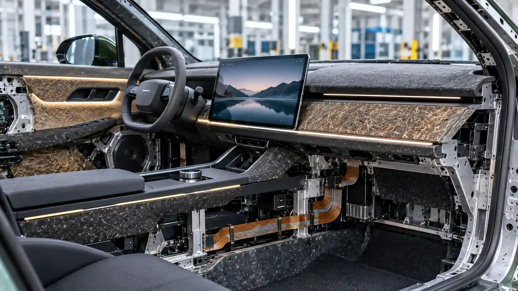
The public conversation about electric vehicle (EV) sustainability is dominated by the battery. That is understandable: the traction pack is the heaviest, costliest and most carbon-intensive single component, and its chemistry determines range, charging speed and a large share of embedded emissions. But a vehicle is a system of systems, and the battery accounts for a minority of its parts. The remainder, the cabin, glazing, electrical distribution network and lighting, comprises thousands of components whose design determines how much material is used, how much mass the powertrain must carry and, at end of life, whether anything can be recovered at an economic cost.
This audit examines those secondary systems through an industrial engineering lens. It looks at how monomaterial polymer design changes the economics of interior recycling, at the thermodynamic and mechanical limits of putting recycled glass into laminated glazing, at the copper, aluminium and routing implications of zonal flat-ribbon wiring, and at how solid-state lighting and capacitive surfaces remove parts and failure modes. It is written for automotive interior design directors, supply chain procurement managers and environmental lifecycle assessors who need to know where the real, quantifiable opportunities lie.
Why secondary systems matter
The complexity burden outside the drivetrain
An EV drivetrain is mechanically simpler than its combustion predecessor. The rest of the vehicle has not followed. A modern cabin can contain over a thousand parts, moulded from a dozen polymer families, wrapped in textiles and films, bonded with adhesives and joined to metal brackets with clips and fasteners. The electrical system may contain several kilometres of copper wire in a harness with hundreds of connectors, individually crimped and routed. Lighting and controls multiply the number of housings, lenses, switches and wiring stubs. Each of these elements was designed to solve a local problem such as a comfort target, a regulatory requirement or a styling theme, and the cumulative effect is a vehicle that is heavy, costly to assemble and almost impossible to separate into pure material streams at end of life.
The end-of-life reality
When a vehicle is scrapped, the metal-rich body, engine and (increasingly) battery are recovered because they have positive value. What remains after shredding and metal separation is automotive shredder residue (ASR), a mixed fraction of plastics, foams, textiles, glass, rubber and dirt that typically accounts for around a fifth to a quarter of the vehicle's mass. Most ASR has been landfilled or incinerated for energy recovery. European policy, through the End-of-Life Vehicles Directive and the proposed regulation that would replace it, is tightening recycling and recycled content requirements, including targets for the proportion of recycled plastic in new vehicles. The practical consequence is that the interior and electrical systems, long treated as an afterthought in recycling, are becoming a compliance and cost issue for manufacturers.
Dematerialisation as the first principle
The most effective circular strategy is to use less material in the first place. A kilogram not fitted is a kilogram that never needs to be mined, manufactured, transported, carried through the vehicle's life or recycled. For an EV, the mass benefit also compounds: lighter vehicles require less energy per kilometre, and a lighter body and chassis can use smaller brakes, suspension and, potentially, a smaller battery for the same range. A common rule of thumb, derived from vehicle simulation, is that a 100 kg reduction in kerb weight reduces EV consumption by roughly 1 to 2 per cent in mixed driving, with a larger benefit in urban conditions. The sections that follow show where secondary systems can contribute.
Monomaterial interior polymer chemistry
The conventional multi-layer dashboard
A traditional instrument panel is a composite structure. A rigid substrate, usually polypropylene filled with talc or glass fibre, or an acrylonitrile butadiene styrene and polycarbonate blend (ABS/PC), provides the structural carrier. Over this sits a layer of polyurethane (PU) or polyolefin foam for soft touch and energy absorption, and a skin of polyvinyl chloride (PVC), thermoplastic polyolefin (TPO) or leather, with grain and colour. The layers are bonded by adhesives, flame lamination or in-mould processes. The result delivers the right feel, appearance and crash performance, but it combines at least three incompatible polymer families, plasticisers and stabilisers into an inseparable laminate.
At end of life, such a part cannot be mechanically recycled into a useful polymer. Shredding it mixes the components, and melting them together produces a brittle, discoloured blend of poor mechanical properties, because most polymers are thermodynamically immiscible. The entropy of mixing for high-molecular-weight chains is very small, so incompatible polymers separate into distinct phases with weak interfaces. PVC is a particular problem: it releases hydrochloric acid on heating, contaminates polyolefin and PET streams, and contains plasticisers that migrate. Polyurethane foams are thermosets or crosslinked elastomers that cannot be remelted.
The monomaterial principle
A monomaterial interior uses a single polymer family, or a set of compatible variants, for substrate, soft layer, skin and textile. The leading candidates are polypropylene (PP) and polyethylene terephthalate (PET). Polypropylene can be formulated across a wide range of stiffness, from rigid filled grades for structural carriers to foamed and thermoplastic elastomer grades for soft-touch surfaces, and can be spun into fibres for fabrics. PET, widely available as post-consumer bottle flake, can be converted into fibre for seat fabrics, headliners, carpets and acoustic insulation, and into film and rigid mouldings. Both are thermoplastics that can be melted and reprocessed.
The engineering advantage is the removal of interfaces. If the carrier, foam and skin are all polypropylene, the finished part can be shredded and pelletised without separation, and the recyclate remains a polypropylene stream with defined properties. There are no adhesive layers to contaminate the melt, no incompatible polymers to cause phase separation and no need for time-consuming manual disassembly. Where adhesives are unavoidable, they can be selected to be of the same polymer family, or replaced by thermal or ultrasonic welding, mechanical clips designed for removal, or in-mould lamination between compatible layers.
Polymer degradation and recyclate quality
Mechanical recycling is not lossless. Every melt-processing step subjects polymer chains to heat, shear and oxygen. In polypropylene, the dominant degradation mechanism is chain scission: the tertiary hydrogen on the polymer backbone is readily abstracted, forming radicals that cleave the chain. Molecular weight falls, melt flow rate rises and mechanical properties such as impact strength decline. Stabiliser packages, including phenolic antioxidants and phosphites, are consumed with each cycle and must be replenished. In PET, hydrolysis in the presence of moisture at melt temperatures breaks ester linkages, reducing intrinsic viscosity. Recyclers address this by drying thoroughly, using chain extenders, or restoring molecular weight through solid-state polycondensation, a process that heats the pellets under vacuum or inert gas to rebuild chain length.
Contamination further degrades quality. Residual inks, dust, other polymers and odour-causing volatile organic compounds limit the share of recycled content acceptable in visible or touch surfaces. Interior parts are subject to strict requirements on emissions, fogging and odour, so recyclate must be decontaminated, typically by vacuum degassing or extraction during extrusion. Colour is another constraint: recycled streams are mixed and grey, so they are best suited to dark or masked components, or require pigment systems that cover a variable base. Design for recycling therefore also includes design for colour, with the industry gradually standardising on dark interiors for high recycled content.
Bio-based polymers
Bio-based polypropylene, derived from vegetable-oil waste or other renewable feedstocks via mass-balance allocation, is chemically identical to fossil polypropylene and behaves in the same way in processing and recycling. It reduces fossil carbon in the feedstock, although life-cycle benefits depend on how the feedstock is produced and allocated. Bio-based polymers that differ chemically, such as polylactic acid, can contaminate petrochemical recycling streams and should be used with care. For lifecycle assessors, the relevant questions are the allocation method, the origin and certification of the biomass and whether the material is compatible with existing recycling infrastructure.
Performance trade-offs
The shift to monomaterial is not free of compromise. Soft-touch feel, scratch resistance and grain definition, which are attributes customers notice, are traditionally delivered by PVC and PU skins. Thermoplastic polyolefin skins and textile-like surfaces offer alternatives, but achieving premium haptics without multi-layer construction takes development. Acoustic damping and energy absorption, provided by foams, must be met by structured or foamed single-material parts. Flammability standards for interior materials (such as FMVSS 302 and equivalent regulations) must be met with minimal additive loading, since flame retardants impair recyclability. These are solvable engineering problems, but they require design effort and often tooling changes.
| Secondary Vehicle System | Baseline Engineering Complexity Level | Primary Circular Feedstock Material | Processing and Manufacturing Optimisation | End-of-Life Material Recovery Potential |
|---|---|---|---|---|
| Cabin trim and upholstery | High: multi-layer laminates of PVC or PU skin, foam, adhesive and substrate across many parts. | Recycled PET fibre and film; recycled and bio-attributed polypropylene. | Single-polymer construction, welding in place of adhesives, fewer parts and dark colourways for recycled content. | High if monomaterial and separable; direct shredding and pelletisation into a defined polymer stream. |
| Structural glazing | Medium to high: laminated panes with PVB interlayer, coatings, ceramic frits and bonded sensors. | Cullet from post-consumer and manufacturing glass in the melt; chemically strengthened thin panes. | Thinner plies with chemical strengthening, tight cullet quality control and lower melt temperatures. | Moderate: glass is infinitely recyclable in principle, but laminate separation and contamination limit current rates. |
| Electrical distribution | Very high: kilometres of point-to-point copper wire, hundreds of connectors and manual assembly. | Recycled copper; aluminium conductors; recyclable insulation polymers. | Zonal topology with flat-ribbon conductors, automated routing and reduced connector count. | High for copper and aluminium via granulation and separation; insulation recovery remains difficult. |
| Lighting and control surfaces | High: discrete switches, housings, bulbs or LED modules and dedicated wiring stubs. | Recycled polycarbonate and PMMA for light guides and lenses. | Printed light guides, capacitive touch films, in-mould electronics and fewer moulded components. | Moderate: single-polymer substrates are recyclable, but embedded electronics need separation. |
Recycled structural glass and glazing mechanics
Why glazing is a mass lever
Glass is dense, about 2.5 grams per cubic centimetre, so each millimetre of thickness weighs about 2.5 kg per square metre. A typical passenger car has between 3.5 and 5 square metres of glazing, and in many EVs with panoramic roofs and large windscreens the area is greater. A conventional laminated windscreen consists of two plies of soda-lime glass, each about 2.1 mm thick, bonded by a 0.76 mm polyvinyl butyral (PVB) interlayer. Reducing total glass thickness is therefore a direct route to dematerialisation: shifting from a 2.1/2.1 mm laminate to a 1.6/1.1 mm laminate removes 1.5 mm of glass, about 3.75 kg per square metre, which on a windscreen of 1.5 square metres amounts to nearly 6 kg. Applied across all glazing, savings of 6 to 12 kg per vehicle are realistic, a modest figure in isolation but significant given the low cost of the change relative to other mass-reduction measures.
Chemical tempering of thin panes
Thin glass is weaker against impact and bending, so the strength must come from another source. Thermal tempering, which heats the glass and quenches it to create surface compression, becomes ineffective below about 3 mm because the thermal gradient needed cannot be established across a thin section. Chemical strengthening provides an alternative. The glass, typically an alkali aluminosilicate composition, is immersed in a molten potassium nitrate bath at around 400 degrees Celsius. Smaller sodium ions in the glass surface exchange with larger potassium ions from the bath. The larger ions crowd the surface, creating a compressive stress layer that may reach 500 to 900 MPa at depths of 30 to 50 micrometres. Because surface flaws propagate under tension, the compressive layer must be overcome before a crack can grow, greatly raising effective strength and impact resistance.
The approach has trade-offs. The compressive layer is shallow, so deep scratches that penetrate it reduce strength sharply. Stored elastic energy affects fragmentation behaviour, and laminate design must be validated against head-impact, stone-impact and pedestrian-protection requirements. Chemical strengthening adds a batch process step, with energy use, salt management and cycle times that must be balanced against the mass saving. The specialised glass compositions used are typically more expensive than float soda-lime glass.
Cullet in the melt
Cullet is crushed recycled glass added to the batch of raw materials in a furnace. Because it is already chemically reacted, it melts at a lower temperature and requires less energy than virgin batch, which must first decompose carbonates and react silica. Industry figures indicate that each 10 per cent of cullet in the batch reduces furnace energy by roughly 2 to 3 per cent, and reduces carbon dioxide emissions by a larger proportion because it displaces process emissions from carbonate decomposition. Container glass furnaces routinely operate with 60 to 90 per cent cullet.
Automotive glazing is far more demanding. Optical quality, strength and consistency are critical, and the glass must be free of defects that would impair vision or cause spontaneous fracture. The principal constraints are contamination and compositional control. Ceramic fragments, stones and refractory particles in cullet do not melt at furnace temperatures and form inclusions, which act as stress concentrators. In thermally tempered glass, nickel sulphide inclusions can undergo a slow phase transformation with volume increase, causing delayed spontaneous breakage. Metallic contaminants tint the glass or create bubbles, and variations in iron content change optical transmission and solar properties. For these reasons, cullet used in automotive float glass is mostly in-plant manufacturing cullet or carefully sorted, high-purity post-consumer flat glass, not general collected container glass. Chemically strengthened aluminosilicate glass is even more sensitive, because its composition is tightly controlled to ensure ion exchange performance, so recycled content in these compositions is currently low and depends on closed-loop recycling of the same glass type.
Laminate recovery at end of life
The laminated structure complicates recycling. Separating glass from PVB requires crushing and mechanical delamination, after which the glass cullet can be cleaned and the PVB recovered for downgraded uses. Without this process, laminated glass ends up in landfill or low-value aggregate. Improving circularity requires collection systems for end-of-life vehicle glazing, investment in separation plants and design measures such as limiting frit area, avoiding unnecessary coatings and keeping sensors and antennas removable. Where glazing is replaced during a vehicle's life, as windscreens commonly are, repair networks offer a ready channel for controlled collection of high-quality material.
Zonal wiring and flat-ribbon distribution
The legacy point-to-point harness
The conventional vehicle harness is a bundle of individual wires running from each sensor, actuator and control unit to the electronic control unit (ECU) that serves it, often via a central junction box. Each function has its own conductors, and signals are carried point to point. A mid-range vehicle can contain 1.5 to 3 kilometres of wire, a premium vehicle more, with several hundred connectors and thousands of crimped terminals. The harness weighs typically 30 to 60 kg, making it one of the heaviest components in the vehicle after the body, powertrain and chassis, and its copper content is a significant fraction of the vehicle's total copper demand.
Manufacturing the harness is notoriously labour-intensive. Wires are cut, stripped and crimped by machine, but the assembly of the bundle on a layout board, the insertion of terminals into connector housings, the taping and the fitting of clips remain largely manual operations, often performed in low-labour-cost regions. Each harness is specific to a vehicle variant and options package, creating a large number of part numbers and complexity in logistics. Installation in the vehicle is also manual, as the harness is threaded through the body in a sequence that cannot be easily automated.
Zonal architecture
A zonal architecture reorganises the electrical system by physical location instead of function. The vehicle is divided into several zones, typically four to six, each served by a zone controller that connects the sensors and actuators nearby through short local wiring. The zone controllers are linked by a high-bandwidth backbone, usually automotive Ethernet and a power distribution ring, to a central computer. This replaces long runs of dedicated wire with short local connections and a small number of shared trunk lines, with the network protocols carrying signals that previously required separate conductors.
The benefits are structural. Total wire length falls, with reductions of 20 to 30 per cent frequently cited, and some manufacturers claim more. Connector counts fall, harness variants are reduced as customisation shifts to software, and the harness becomes more modular and more amenable to automation. Mass falls with conductor length. The architecture also supports over-the-air updates and new features without hardware changes, because functions are defined in software on the zone controllers.
Flat-ribbon conductors
Within zones and along the backbone, flat conductors offer further benefits. Flat flexible cable (FFC) and flexible printed circuit (FPC) technologies use thin rectangular conductors, laminated between insulating films, in place of round insulated wires. Flat geometry has a high surface area to volume ratio and so dissipates heat well, enabling smaller cross-sections for a given current. Thickness can be as low as a fraction of a millimetre, allowing routing under carpets, in door seals and along trim. Because the conductors are laid out in a precise geometry, flat cables can be produced in continuous automated processes and installed with fewer manual routing steps. Connectors can be integrated as insulation displacement or crimp-on terminations to standardised interfaces.
The conductor material choice adds another dimension. Aluminium has a resistivity about 1.6 times that of copper, so for the same resistance, an aluminium conductor needs about 1.6 times the cross-sectional area. Because aluminium's density is only about 30 per cent of copper's (2.7 against 8.96 grams per cubic centimetre), the mass for equal resistance is approximately 0.48 of the copper equivalent, so aluminium conductors weigh roughly half as much as the copper they replace. Aluminium is also cheaper per tonne and less price-volatile than copper. The engineering challenges are well known: aluminium forms a surface oxide that increases contact resistance, has lower fatigue resistance, creeps under sustained mechanical load and suffers galvanic corrosion when in contact with copper terminals in the presence of moisture. Solutions include specialised terminals, plating, sealed connections and welding or ultrasonic bonding to produce reliable joints, and these have been proven in high-volume applications.
Quantifying the saving
An illustrative calculation shows the scale. Take a legacy harness of 45 kg, of which approximately 30 kg is copper conductor and 15 kg is insulation, connectors and clips. A zonal architecture that cuts wire length by 25 per cent reduces copper to about 22.5 kg and insulation and connectors to perhaps 11 kg, giving a harness of about 34 kg, a reduction of roughly 25 per cent. If a further 40 per cent of the remaining copper, 9 kg, is replaced by aluminium at 0.48 times the mass, that portion weighs about 4.3 kg, and the total conductor mass falls to about 17.8 kg. With insulation and connectors, the harness weighs about 29 kg, a 36 per cent reduction from the original. Copper use falls from 30 kg to 13.5 kg per vehicle, a drop of more than half, with significant consequences for resource demand and cost at fleet volumes. These figures are illustrative and depend heavily on vehicle architecture, but they indicate the order of magnitude that manufacturers claim.
Recycling the harness
Harnesses are valuable at end of life because of their metal content. Typical practice is to remove harnesses during dismantling or recover them from shredder fractions, then granulate the cable, separating copper from insulation by density or electrostatic methods. Copper from this route is of high quality. Aluminium conductors, mixed with copper in the stream, require separation to avoid contaminating copper melt, an additional sorting step. Insulation polymers, commonly PVC or cross-linked polyethylene, are harder to recycle. Shifting to halogen-free, thermoplastic insulation such as polyolefins or polyesters improves recyclability. Flat-ribbon cables laminated between polyester films are separable in principle but present a thin, mixed structure that needs development of tailored recovery processes.
Solid-state lighting and smart surfaces
The conventional lighting and switch assembly
Traditional cabin lighting and controls rely on discrete components. Each switch is a mechanical assembly with a housing, a moving actuator, metal contacts, a spring and a connector, wired back to a control unit. Each lamp or LED module sits in its own moulded housing with a lens, reflector and connector. A vehicle may have dozens of switches and many separate lighting points, each requiring tooling for its plastic parts, assembly labour and wiring. Mechanical switches wear out: contacts oxidise, springs fatigue and the ingress of liquids or dust causes failures. These are among the common causes of cabin electrical faults and warranty claims.
Light guides and printed illumination
Solid-state alternatives replace point sources and housings with distributed illumination. A light guide is a transparent polymer element, typically PMMA or polycarbonate, that carries light from a small number of LEDs along its length by total internal reflection and emits it through engineered surface features. A single guide can provide ambient lighting along a dashboard or door trim, replacing a string of individual lamps. Printed or film-based light guides, which use microstructured layers or laminated films, can be thin and flexible, integrated into trim surfaces. A small number of LEDs and a single driver can then illuminate large areas.
The component count falls sharply. Fewer lamp housings, fewer connectors and shorter wiring reduce plastic moulding, assembly operations and the number of potential failure points. LEDs are solid-state, with lifetimes of tens of thousands of hours, far exceeding the vehicle's service life, so the failure vectors move from mechanical wear to electronic and software issues. Recyclability depends on keeping the light guide in a single transparent polymer that can be separated from electronics, and avoiding paints and coatings that contaminate the stream.
Capacitive touch and in-mould electronics
Capacitive sensing detects the change in capacitance caused by a finger approaching a conductive electrode. Electrodes can be printed on a film or integrated into a moulded part, so controls can be built into a surface with no moving parts. In-mould electronics (IME) techniques print conductive inks and place components on a film that is then thermoformed and back-moulded with polymer, resulting in a single part with embedded circuitry, illumination and touch sensing. This integration reduces the number of separate parts, eliminates mechanical switches and enables seamless surfaces that are easy to clean and robust against liquid ingress.
There are practical constraints. Capacitive controls provide no tactile feedback, and many safety and usability studies, as well as consumer experience, show that touch-only controls for frequently used functions can increase driver distraction. Regulators and assessment programmes have begun to favour physical controls for safety-critical functions. Haptic feedback through actuators can mitigate this at the cost of additional components. Sensors can be affected by moisture, gloves and electromagnetic interference, requiring careful design. Electronics embedded in polymer also complicate recycling, because separation of circuit films, inks and components from the plastic substrate is difficult. Design for disassembly, such as removable control modules and labelling of electronics, is needed to avoid contaminating the plastic stream.
System-level effects
The overall benefit is a reduction in parts, mass, tooling and wiring. A cabin lighting and control system consolidated into a few printed modules might replace dozens of discrete components with perhaps a handful, reducing the number of unique part numbers and simplifying logistics. Failure modes consolidate onto electronics and software, which can be diagnosed, updated and, in many cases, repaired remotely. The principal risks are the usability and regulatory constraints on touch controls, and the end-of-life separation of embedded electronics.
Systemic integration and lifecycle assessment
The interactions between systems
The four systems are not independent. Zonal wiring reduces the number of wires passing through interior trim, simplifying panel design and facilitating monomaterial construction. Printed light guides and capacitive surfaces reduce wiring in doors and dashboards, which supports zonal consolidation. Thinner glazing reduces roof and door mass, allowing lighter structures. Treated together, these changes form a design philosophy of fewer parts, fewer materials and fewer interfaces, with consequent benefits in assembly time, inventory and recyclability.
What lifecycle assessment should measure
For environmental lifecycle assessors, a credible evaluation of these measures requires specific metrics. Embedded emissions per kilogram of each material, including recycled and bio-based variants, form the basis of the inventory. Use-phase impacts depend on the mass saved and the energy mix of the charging electricity: for a cleaner grid, the use-phase benefit of mass reduction is smaller, which increases the relative importance of manufacturing and end-of-life impacts. End-of-life scenarios should be modelled realistically, using actual recovery rates for each material stream, not theoretical potential. Recycled content claims should be checked against the allocation method used, such as cut-off or avoided burden, because the choice significantly changes reported benefits. Finally, durability and repairability matter: a design that lasts longer or can be repaired avoids the impact of replacement.
Economics and procurement
Circular design must also make commercial sense. Monomaterial interiors can reduce part counts and assembly cost, but recycled polymer grades may cost more than virgin material at present, depending on market conditions and quality requirements. Aluminium conductors save raw material cost but require investment in terminals and process validation. Chemical strengthening adds process cost that offsets part of the material saving. Procurement managers should evaluate total cost of ownership including tooling, labour, logistics and compliance with recycled content regulations, and consider long-term supply agreements for recycled materials to secure quality and price stability. Supplier capability, particularly in recycled polymer compounding, glass cullet quality control and aluminium wire processing, is a critical selection factor.
Recommendations for design directors, procurement managers and assessors
- Design for a single polymer family. Specify PP or PET throughout the interior where performance allows, replace adhesives with welding or compatible bonding and avoid PVC and thermoset foams.
- Specify recycled content with quality limits. Define permissible recyclate grades, odour and emission limits and colour strategy early, and secure supply through long-term agreements.
- Reduce glazing thickness with validated chemical strengthening. Verify impact, scratch and fracture performance, and ensure cullet quality control to avoid inclusions.
- Move to zonal architecture. Combine zonal controllers with flat-ribbon distribution, and evaluate aluminium conductors where termination technology is proven.
- Consolidate lighting and controls. Use printed light guides and capacitive surfaces for low-criticality functions, and keep physical controls for safety-critical and frequently used functions.
- Plan for disassembly. Make embedded electronics removable, label materials and design components so that high-value streams can be recovered without extensive manual labour.
- Quantify with a realistic lifecycle model. Use actual end-of-life recovery rates, transparent allocation methods and sensitivity analysis on grid carbon intensity.
Conclusion: the circular vehicle is designed outside the chassis
The drivetrain has received the greater share of attention in automotive decarbonisation, but a large part of a vehicle's material complexity, mass and end-of-life problem lies in systems that rarely feature in headlines. Monomaterial interiors replace inseparable multi-layer laminates with single polymer families that can be shredded and pelletised directly. Thinner, chemically strengthened glazing and carefully controlled cullet use lower mass and furnace emissions while preserving impact resistance. Zonal architectures and flat-ribbon conductors cut wire length, connector count and copper demand, with aluminium offering a further halving of conductor mass where the engineering challenges of termination are met. Solid-state lighting and capacitive surfaces remove mechanical parts and housings, with attention to usability and recoverability.
None of these measures is a single breakthrough, and each carries compromises in cost, feel, durability or process. Together, though, they describe a consistent design philosophy: fewer materials, fewer parts and fewer interfaces. For interior design directors, procurement managers and lifecycle assessors, the opportunity lies in treating these secondary systems as a coordinated programme, supported by credible data, supplier partnerships and honest end-of-life modelling. The vehicles that achieve genuine circularity will be those designed from the cabin outward as carefully as they are from the battery upward.